Table of Contents
Design and Fabrication
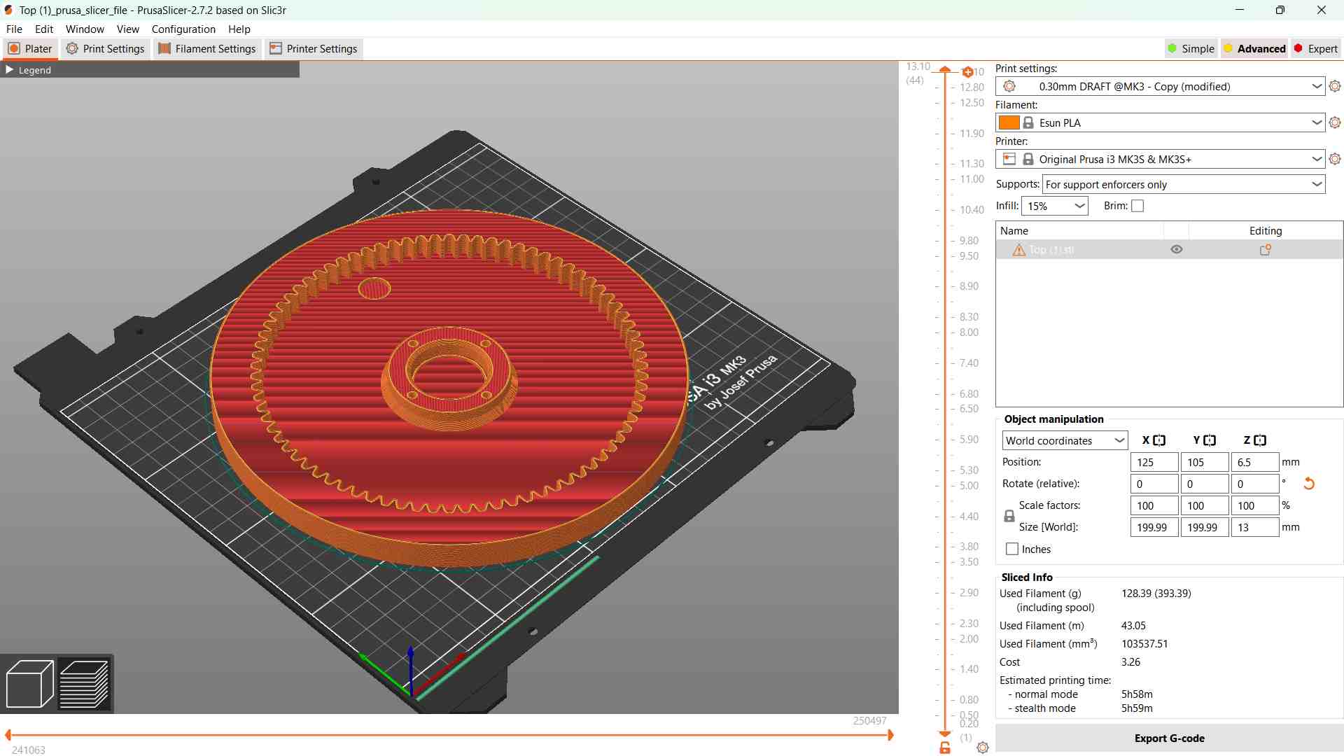
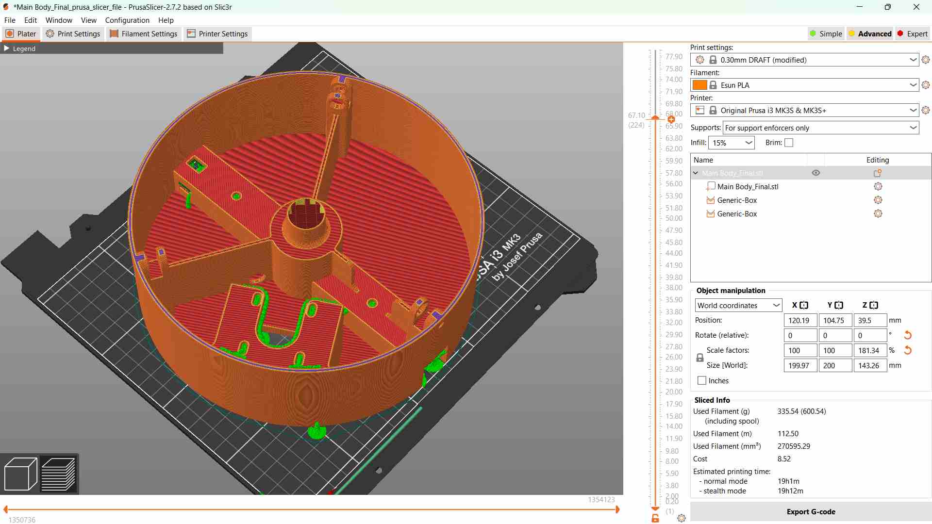
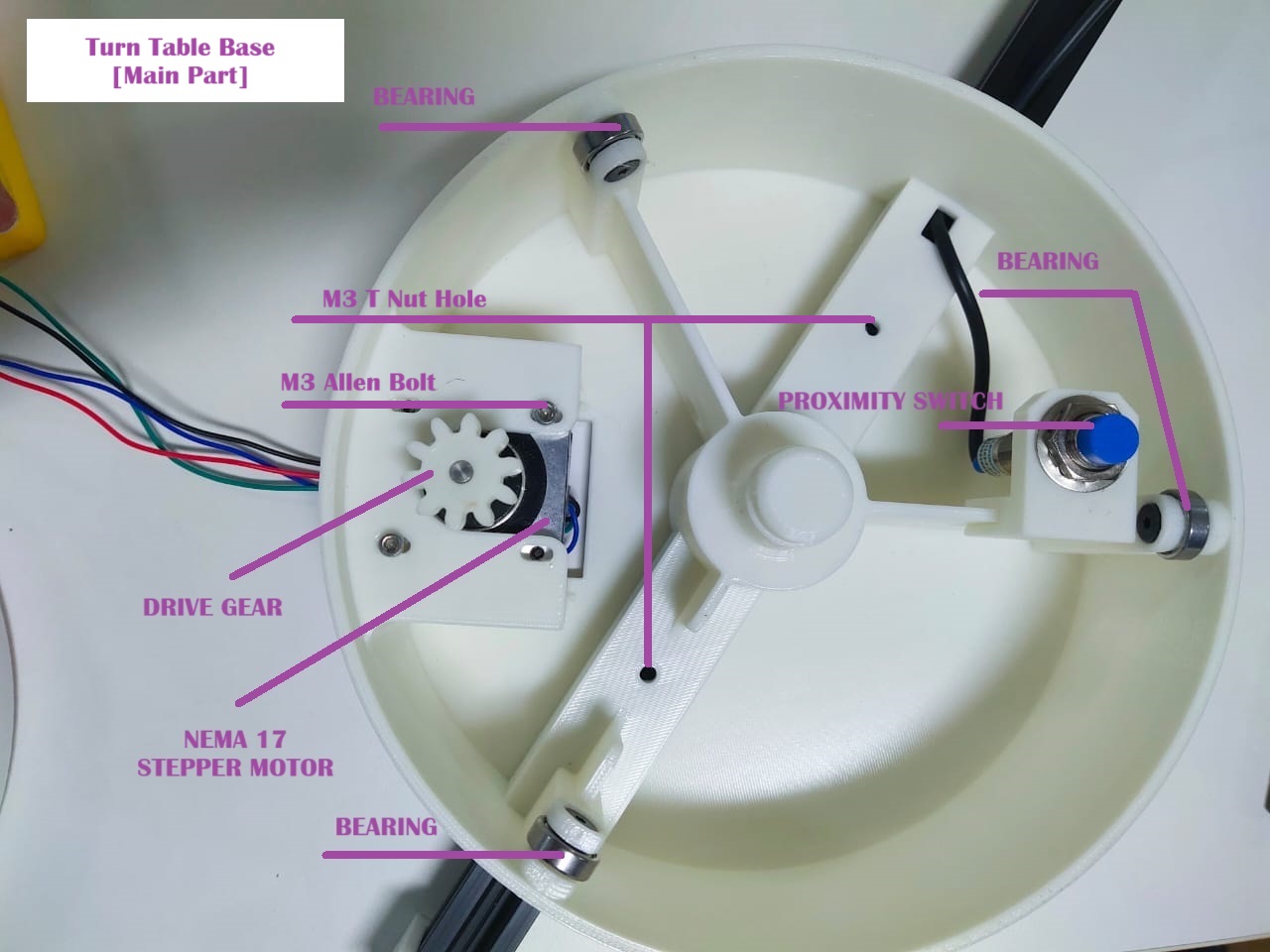
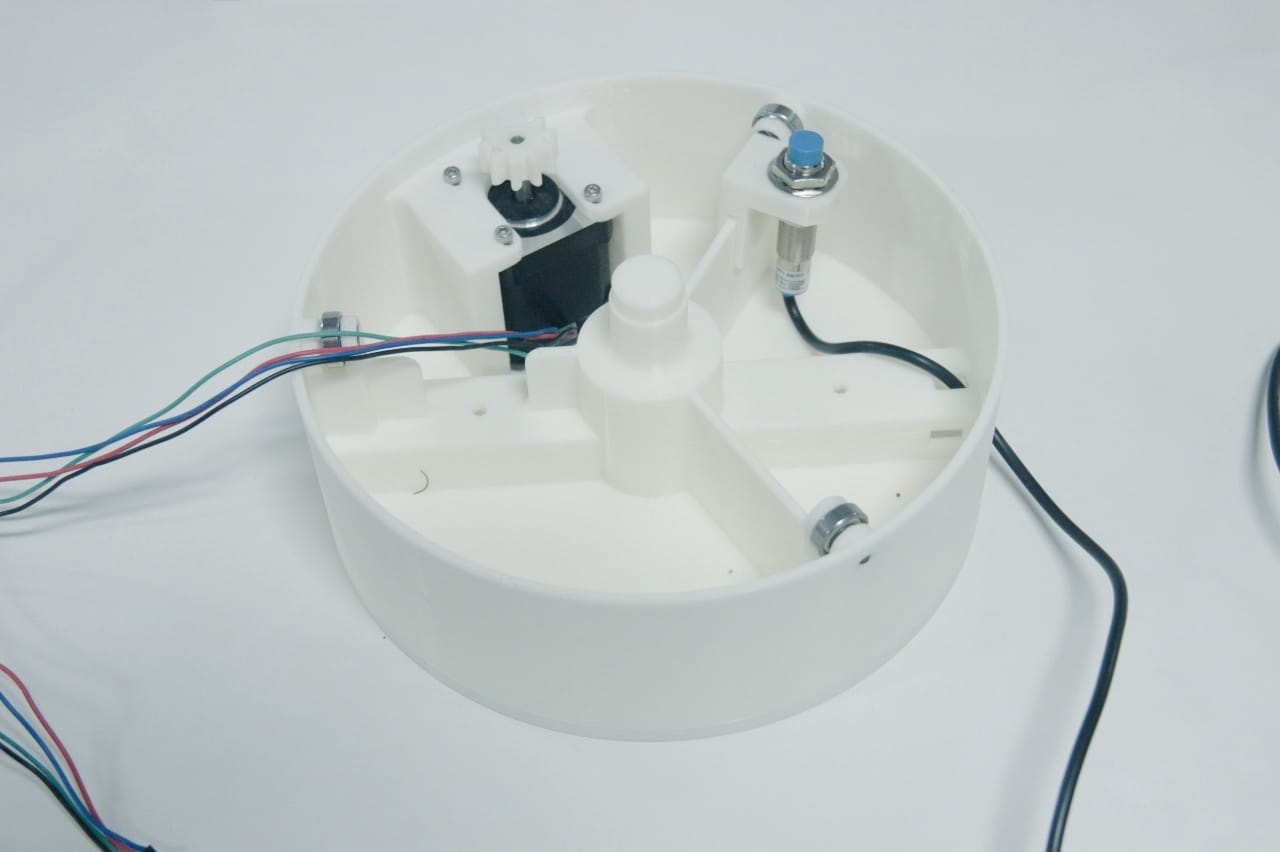
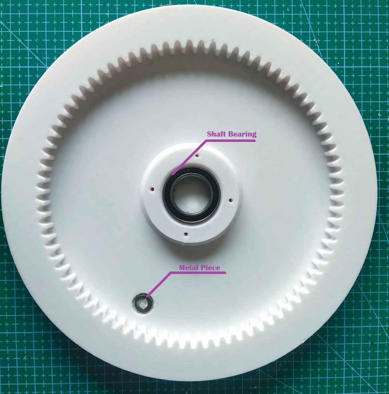
Turn Table Design
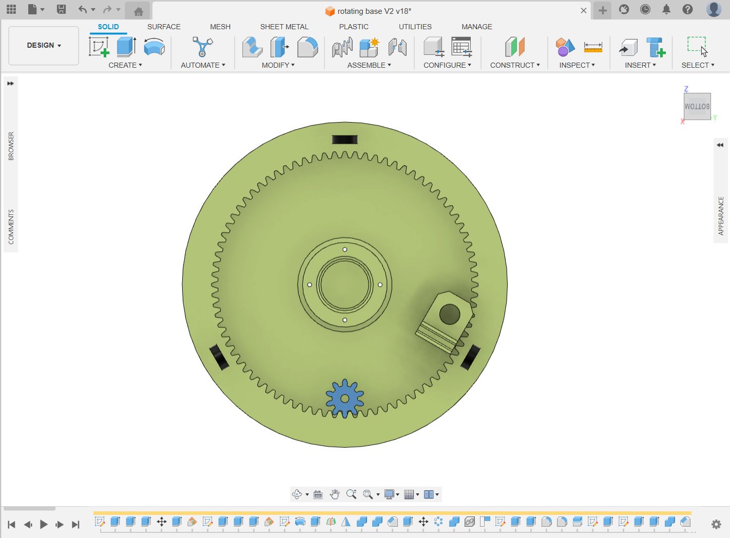
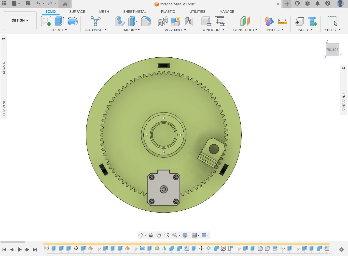
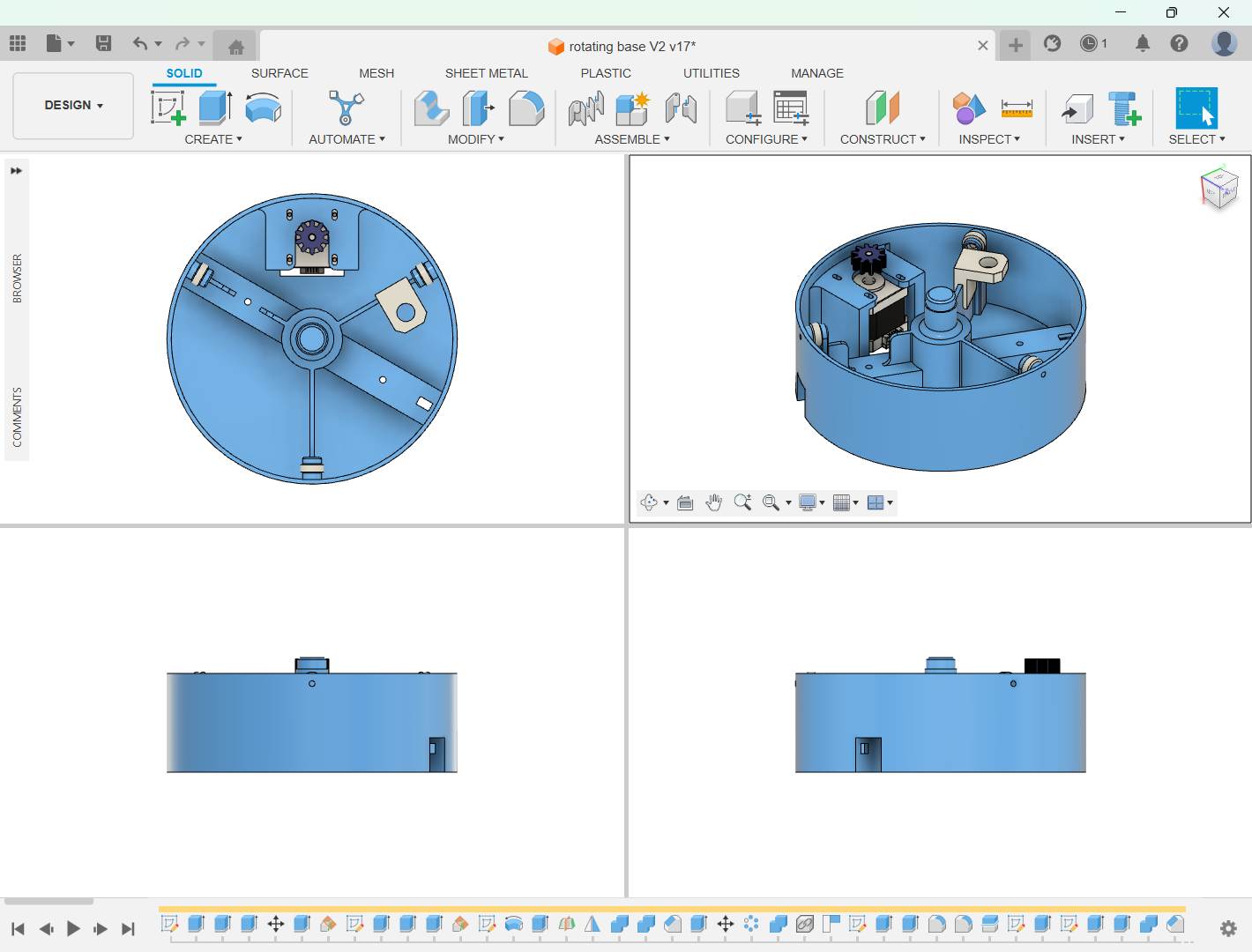
Turn Table Fabrication & Testing
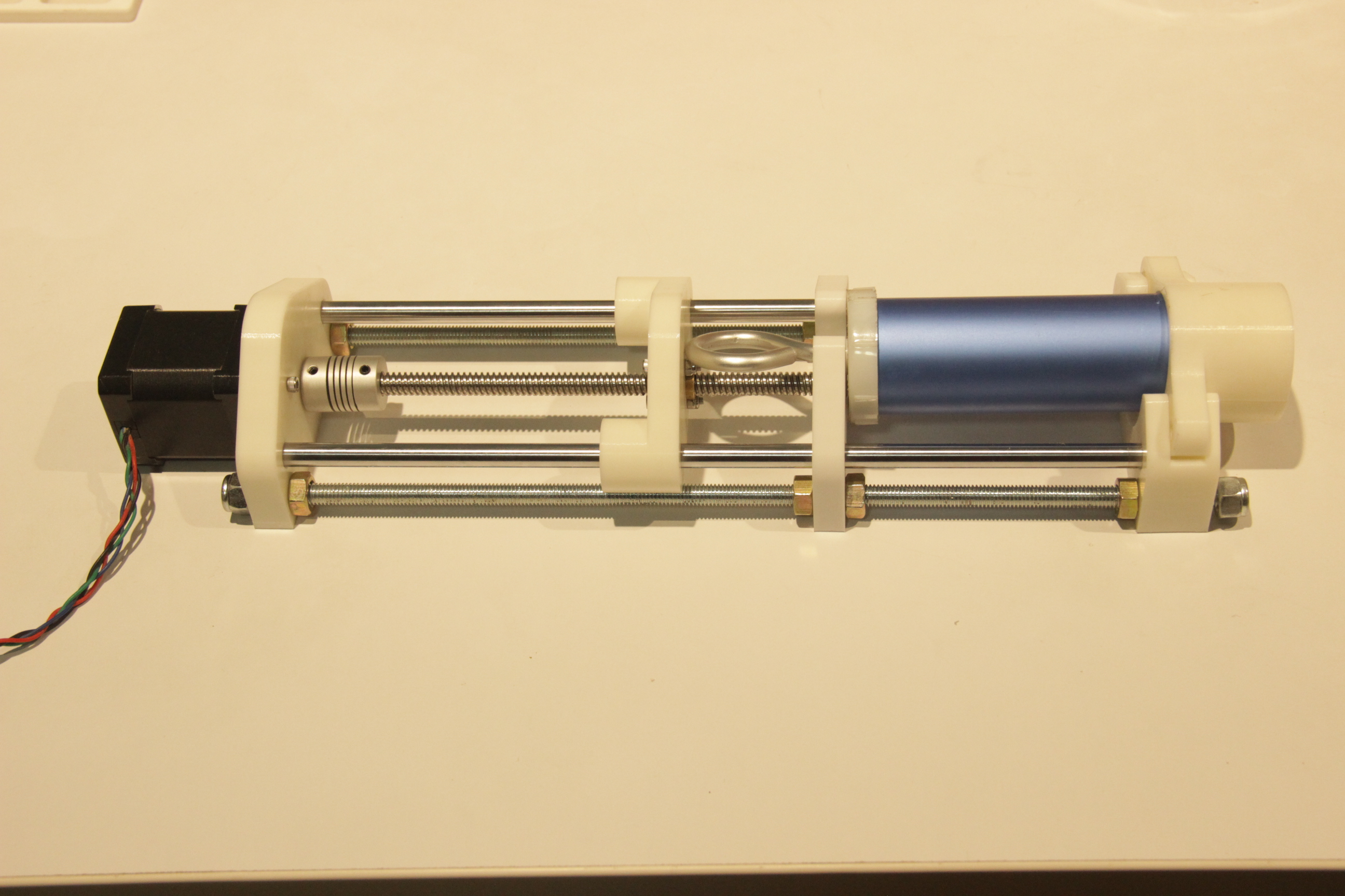
Extruder
Extruder was the main part of the machine , We planned to extrude the frosting externally and created the sketch in fusion for the extruder.
.png)
.png)
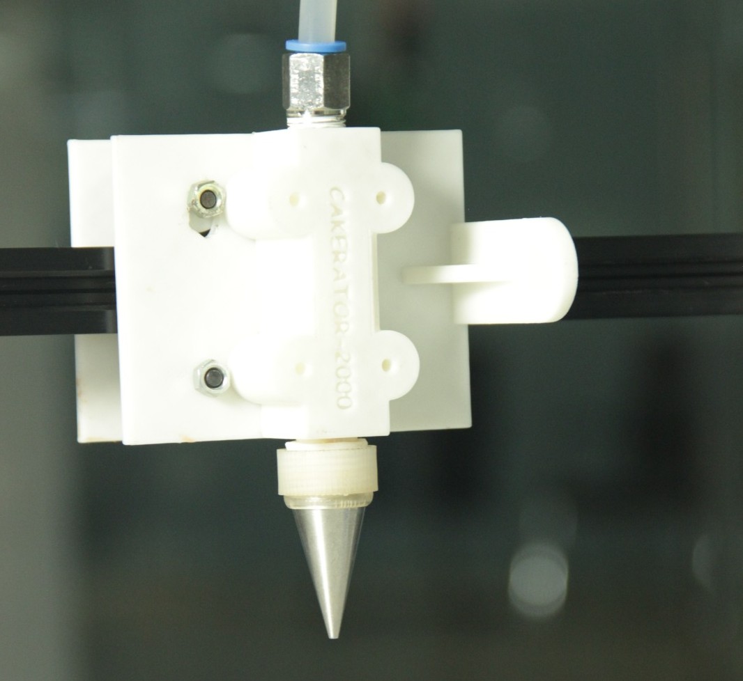
Extruder Fabrication & Testing
We 3D printed the various parts and assembled to get the extruder
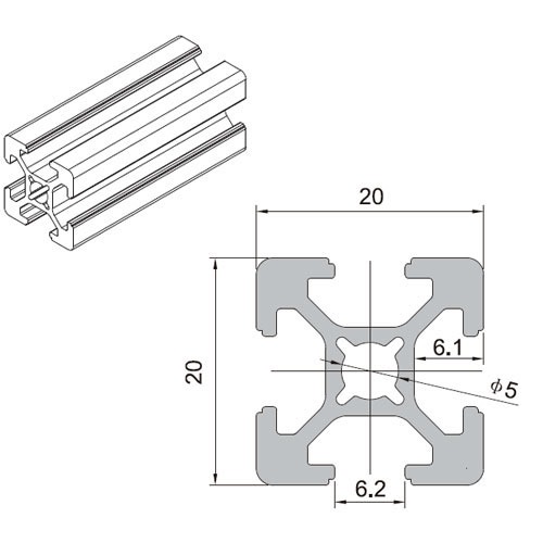
Machine Frame
We planned to make the machine frame with aluminum extrusions. For that, we identified the vendors and purchased the 20 mm extrusion for our machine.
We have designed and 3D printed the joints and assembled the frame with the rest of the parts.
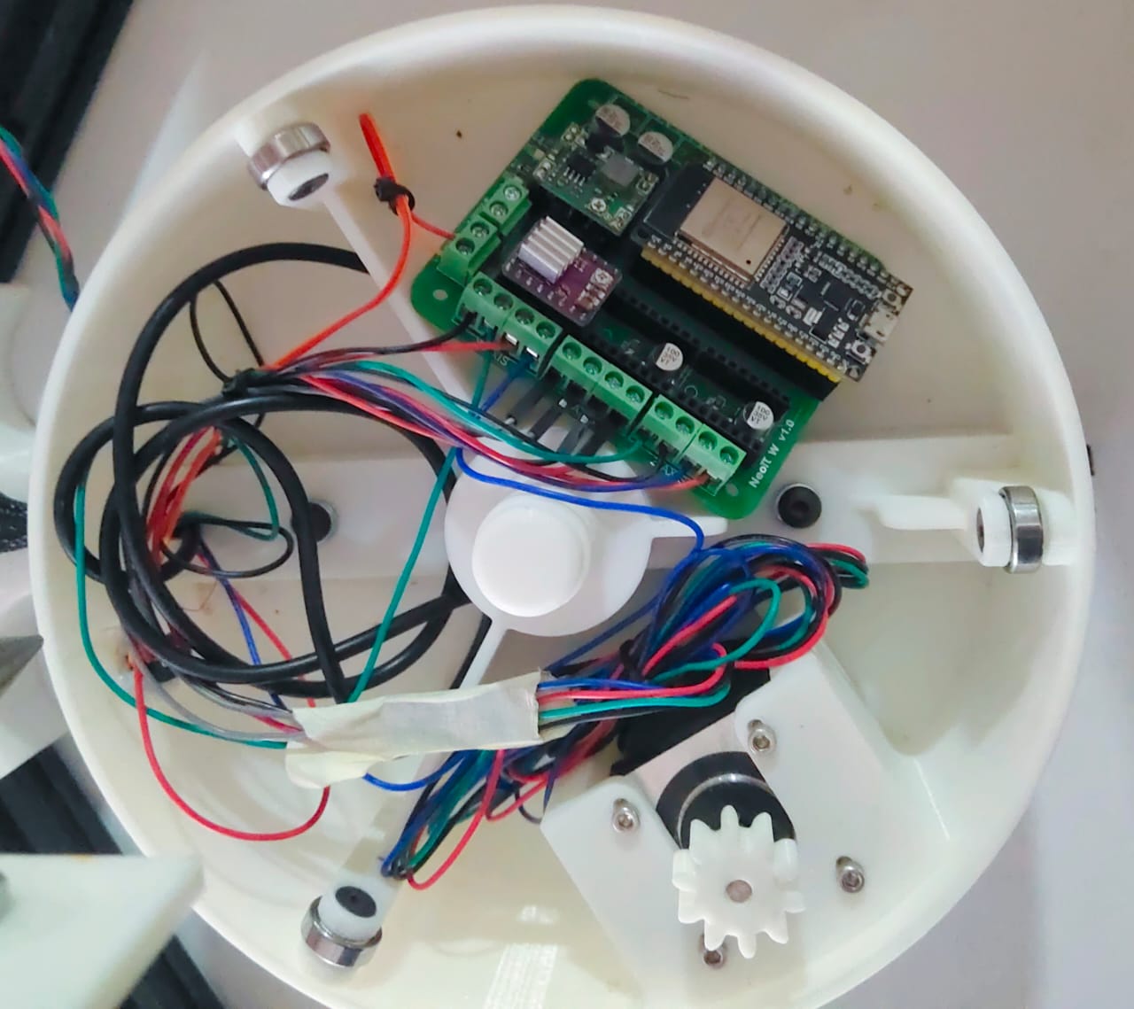
Electronics
Firmware
GRBL
-
The project “Cakerator ” has been developed using the repo at
https://github.com/bdring/Grbl_Esp32/tree/main/Grbl_Esp32which is a specialized project that utilizes the ESP32 microcontroller to run GRBL, an open-source control software designed for CNC (Computer Numerical Control) machines.
- This project essentially adapts GRBL to leverage the advanced features of the ESP32 chip, such as Wi-Fi and Bluetooth connectivity, increased processing power, and more GPIO pins, which can be extremely beneficial for a wide range of CNC applications, from milling machines to laser cutters and beyond
-
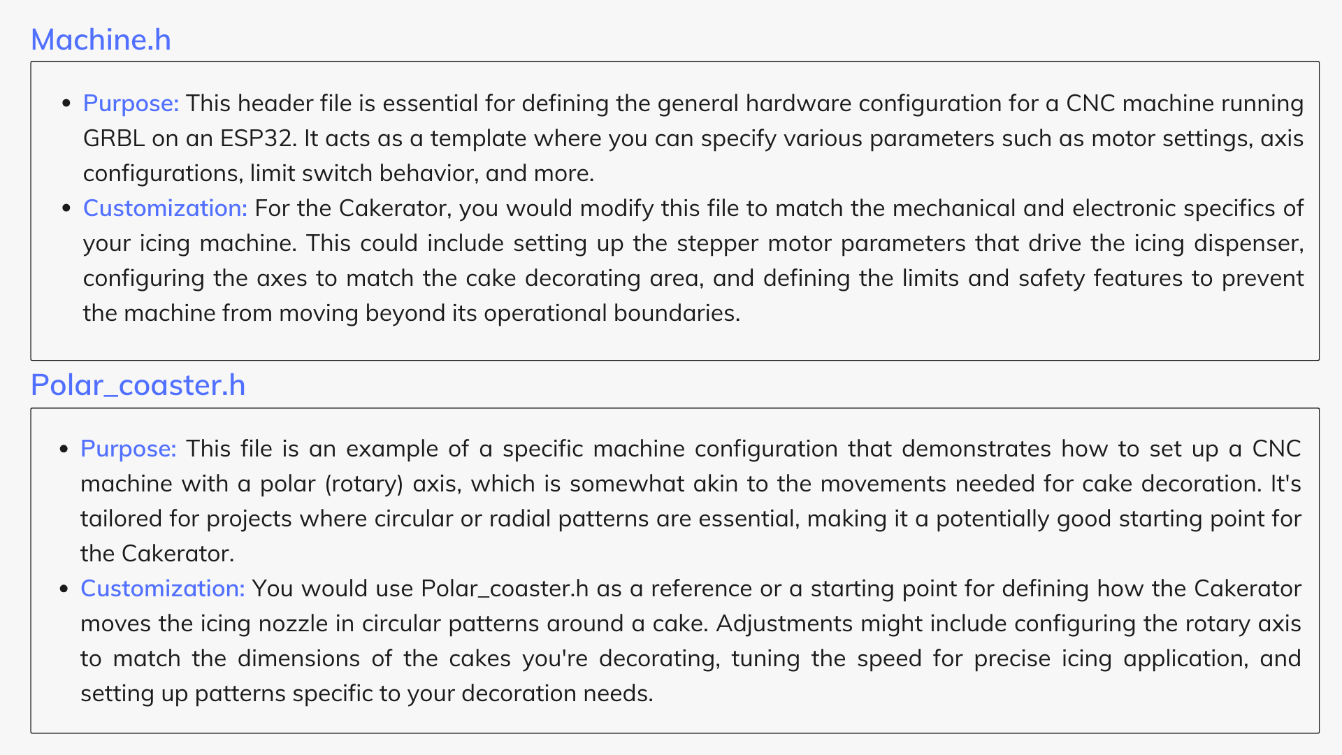
The specific files mentioned,
Machine.handPolar_coaster.h, play crucial roles in configuring the GRBL software for specific hardware setups. Here's how they fit into the customization of your "Cakerator " automatic icing machine:
Working with the GRBL_Esp32 Repository
Steps to customize and use Machine.h and Polar_coaster.h for the Cakerator are provided below.
Step 1: Install PlatformIO
If you haven't already, download and install PlatformIO IDE or PlatformIO Core. The IDE can be used as a plugin for VSCode or Atom, offering a graphical interface and easier project management.
Step 2: Create a new project in PlatformIO
Open PlatformIO and start a new project. Select the ESP32 as your board and specify the location of the cloned repository as the project directory.
Step 3: Clone the Repository
First, you need to clone the GRBL_ESP32 repository to your local development environment to access the files.
git clone <https://github.com/bdring/Grbl_Esp32.git>Step 4: Understand the Default Configurations
Spend some time understanding how the default
Machine.h
and the example
Polar_coaster.h
are set up. This understanding will guide you in customizing these files for your specific hardware.
Step 5: Customize
Machine.h
Based on your hardware's specifications (e.g., motors, axis layout, size), start modifying
Machine.h
to reflect the Cakerator 's setup. This will include setting up motor drivers, defining axis properties, and configuring limit switches.
Step 6: Adapt
Polar_coaster.h
for Circular Movements
Use
Polar_coaster.h
as a base to create a configuration that matches the rotational and linear movements needed for cake decorating. Adjust parameters for the rotary table that holds the cake and the linear axis that moves the icing nozzle.
Step 7: Test and Refine
After configuring the files, compile and upload the firmware to your ESP32 controller. Begin with simple test patterns to ensure that the machine moves as expected. Adjust the configurations as necessary to fine-tune the machine's performance.
Step 8: Develop Decoration Patterns
Finally, develop G-code patterns or software interfaces to design and implement the decoration patterns you wish to apply with the Cakerator .
Using PlatformIO, an open-source ecosystem for IoT development, to work with the GRBL_Esp32 GitHub repository and to identify and configure pins as per a specific file in another repository involves several steps. PlatformIO simplifies the process of compiling and uploading firmware to microcontrollers.
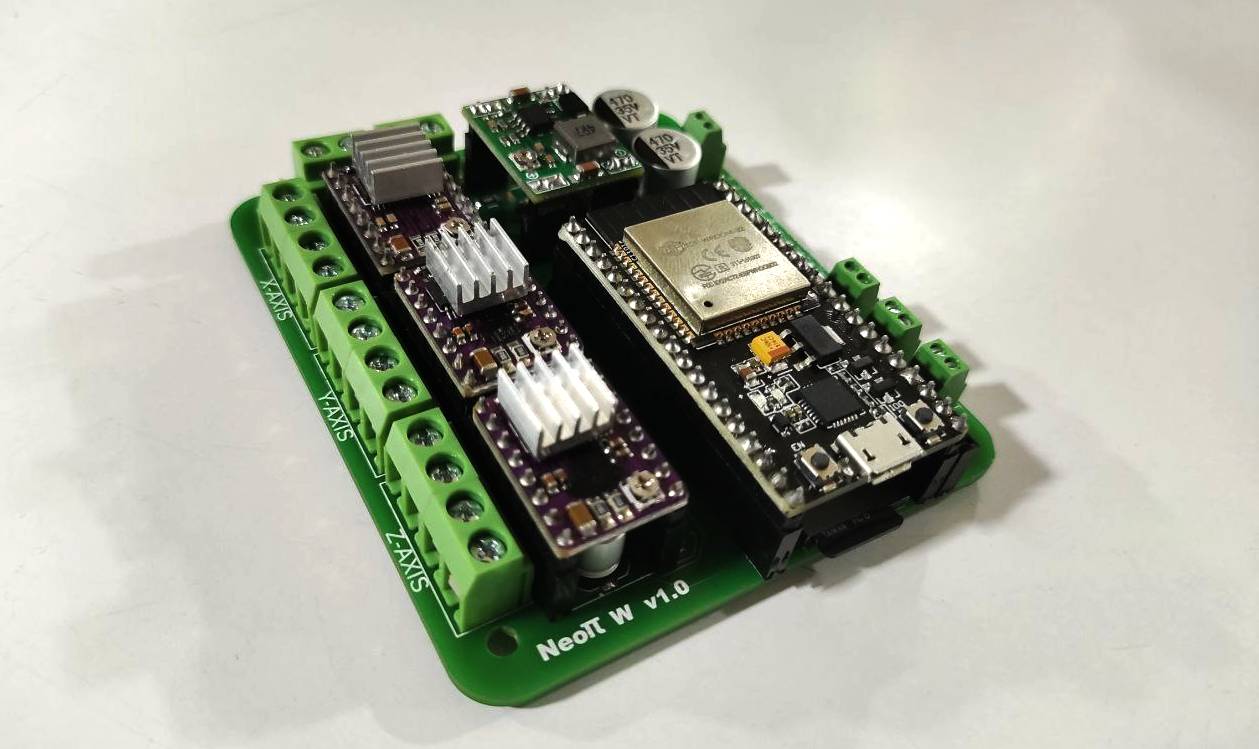
Identifying and Configuring Pins Using the NeoPI_Wireless Repository
Step 1: Review the Pin Configuration
-
Open the
NeoPI_W_v1.hfile from the NeoPI_Wireless repository .
- This file contains definitions for various pins and their roles in the project. It's critical to understand these roles to properly map them onto your hardware.
Step 2: Adapt Pin Configuration for Your Project
-
Based on the pin definitions in
NeoPI_W_v1.h, you'll need to adjust the pin assignments in your GRBL_Esp32 project (likely withinMachine.hor your specific machine configuration file) to match the physical hardware connections of the Cakerator .
Step 3: PlatformIO Project Update
-
After identifying the necessary pin configurations and making adjustments, update your PlatformIO project files accordingly. This may involve editing the
platformio.inifile for any specific library dependencies or environment configurations, in addition to your source code changes.
Step 4: Compile and Upload Again
- With the new pin configurations in place, compile your project again using PlatformIO.
- Upload the firmware to your hardware and conduct tests to ensure the pin mappings are correctly implemented and functional.
Throughout this process, it's vital to thoroughly test each change to ensure compatibility with your hardware setup and desired functionality. PlatformIO's serial monitor and debugging tools can be very helpful for troubleshooting any issues that arise during development.

- The GRBL_Esp32 repository is a notable fork of the original GRBL project, tailored for the ESP32 microcontroller, which offers a significant upgrade in terms of processing power, memory, and connectivity options compared to the microcontrollers traditionally used with GRBL.
- One of the standout features of this adaptation is its support for a Web UI (Web User Interface), enabling users to interact with the CNC machine over a network.
- This feature is especially useful for projects like the Cakerator , where ease of use and flexibility in design and operation can greatly enhance the user experience.
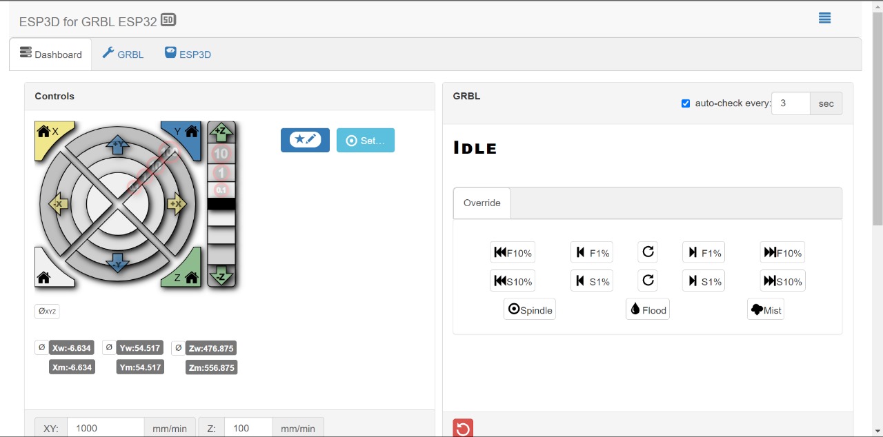
Use of Web UI in GRBL_Esp32
The Web UI allows users to perform a wide range of actions remotely and wirelessly, which includes, but is not limited to, uploading G-code files, monitoring the machine's status, and controlling its operations in real-time. Here's how you can leverage the Web UI for developing and uploading G-codes for making designs:
Setting Up the Web UI
Step 1: Connect the ESP32 to Your Network
After flashing the GRBL_Esp32 firmware to your ESP32, configure it to connect to your Wi-Fi network. This is usually done through a one-time setup over a serial connection, where you provide your network's SSID and password.
Step 2: Access the Web UI
Once the ESP32 is connected to your network, it will be accessible via a web browser. You can find its IP address either from your router's DHCP client list or it might be displayed on the console (serial monitor) of the ESP32 upon startup.
Step 3: Navigate the Web Interface
The Web UI is typically straightforward, offering sections for machine control, job status, file management, and system settings. Its responsive design should work well on both desktop and mobile browsers.
Developing and Uploading G-Codes
Step 1: Design Your Cake Decorations
Using any G-code generating software, design the patterns or text you want to decorate your cake with. Ensure the designs are compatible with the motion capabilities of the Cakerator .
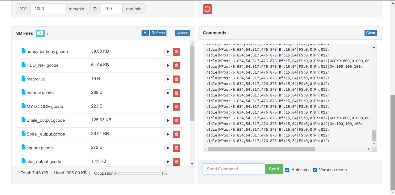
Step 2: Upload G-Code Files
Within the Web UI, navigate to the file management or G-code upload section. Here, you can select and upload the G-code files from your computer to the ESP32's onboard storage or an attached SD card, depending on the setup.
Step 3: Select and Run Your Design
After uploading, you can select the G-code file you wish to execute from the file list in the Web UI. Initiating the job typically involves clicking a "start" or "run" button within the interface.
Step 4: Monitor and Control the Job
While the Cakerator is operating, you can use the Web UI to monitor its progress, pause or stop the job if necessary, and even adjust certain parameters like feed rate and spindle speed in real-time, as your setup and firmware configuration allow.
Benefits of Using the Web UI for Cakerator
Wireless Operation
Eliminates the need for a direct physical connection between the computer and the machine, allowing for more flexibility in the setup.
Ease of Use
Offers a user-friendly interface for uploading and managing G-code files, making it accessible even for users with limited CNC experience.
Real-Time Control and Monitoring
Provides immediate feedback on the machine's status and allows for on-the-fly adjustments, which is crucial for fine-tuning the cake decorating process.
Components and BOM
| S. No | Part | Quantity | Amount | Total Price | Availability |
| 1 | NEMA 17 stepper motors | 3 | 520 | ₹ 1560 | Fab Inventory |
| 2 | Threadrod M8 | 1 | 70 | ₹ 70 | Fab Inventory |
| 3 | 20 mm x 20 mm aluminium extrusion | 1 mtr | 160 | ₹ 160 | Local Shop |
| 4 | M4 Bolt & Nut (Approx Value) | 20 | 8 | ₹ 160 | Fab Inventory |
| 5 | M8 hose | 1 mtr | 190 | ₹ 190 | Fab Inventory |
| 6 | GT2 Pulley | 2 | 135 | ₹ 270 | Fab Inventory |
| 7 | GT2 6 mm belt | 1 mtr | 77 | ₹ 77 | Fab Inventory |
| 8 | Bearing 625ZZ | 4 | 60 | ₹ 240 | Fab Inventory |
| 9 | Proximity Sensor | 2 | 200 | ₹ 400 | Local Shop |
| Total | ₹ 3127 |
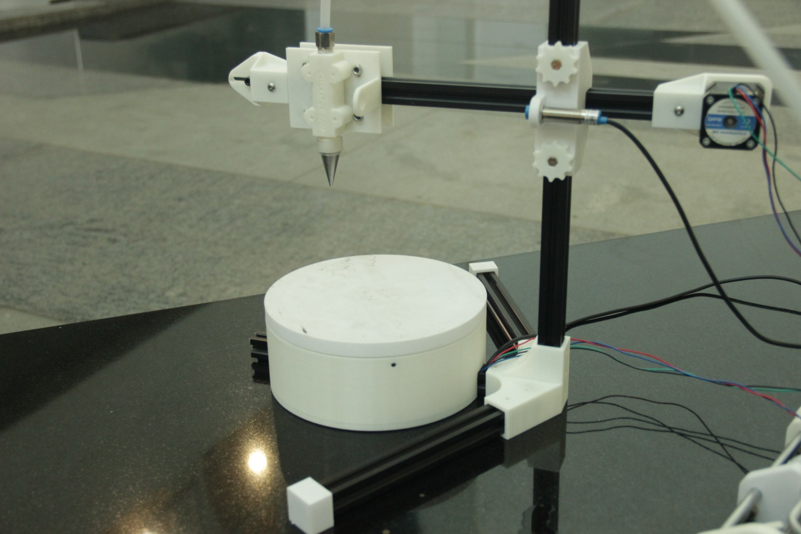
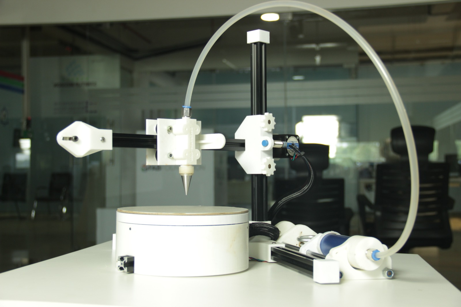
System Integration & Testing
After the GRBL configuration, we tested our machine with Tomato sauce, which was easily available at nearby store and it has some viscosity, just like chocolate Ganache
Final Result
Problems Faced as a Team
We initially started by using buttercream. But because of its consistency, it was very difficult to extrude. The plunger was giving way to the buttercream. We decided to make chocolate ganache, salted caramel and whipping cream to test the plunger.
Out of the three, chocolate ganache was the better option, but we decided to change the consistency from 2:1 (chocolate to cream) to 1:1. This seemed like a better option. However, over time the ganache solidified in the pipe.
Future Improvements
To further enhance the Cakerator , several key improvements can be made to optimize its functionality and performance. Here are detailed areas for improvement.
We are planning to implement a system to automatically control and adjust the viscosity of the cream to ensure consistent flow and application. This could involve sensors that monitor the viscosity and an integrated mixing system that adjusts the cream's consistency in real-time.
Integrating precise temperature control to keep the cream at an optimal temperature can maintain the desired viscosity, especially for different types of cream that may require specific conditions.
Increasing the storage capacity of the extruder can reduce the need for frequent refills, allowing for longer decorating sessions without interruptions. This can be achieved by redesigning the extruder to hold more cream or by adding an auxiliary reservoir that feeds into the main extruder.
Enabling automated control of the Z-axis can allow for precise adjustments of the decorating head's height, facilitating more complex and layered designs. This can be achieved by adding a motorized system controlled by the software, allowing for dynamic changes during the decorating process.