Table of Contents
Achievement

The Concept Behind Poly Plot
Poly Plot is a compact, automated pen plotter designed to bridge digital creativity and physical art. It translates digital vector drawings into precise pen movements, combining mechanics, electronics, and software in one integrated system.
The Idea and Inspiration
Poly Plot – Kerala’s First Multi-Color CNC Plotter with ATC
The Poly Plot is a custom-designed CNC Core XY multi-color plotter developed under the Centre for Early Innovation (CEI) initiative. It was created to showcase the possibilities of digital fabrication and automation within school makerspaces, bringing together creativity, precision, and technology in a single educational machine.
Engineering the System
The Poly Plot is built on a Core XY motion system driven by three NEMA 17 stepper motors for precise and coordinated movement. The frame uses 2060 aluminum extrusions for rigidity and modularity, combined with 3D-printed components for custom fittings and functional assemblies.
Motion control is powered by a custom ESP32-based PCB integrated with DRV8825 stepper drivers, enabling high-speed, accurate plotting and automatic pen changes. The machine includes end stops, drag chains, and a regulated power supply for stable operation.
It features an A1-sized bed, providing ample workspace for creative output. The firmware is built on top of FluidNC, an open-source CNC firmware that translates G-code commands from a custom user interface into real-time motion and pen actuation.
Tools and Technologies Used
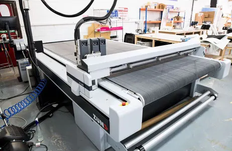
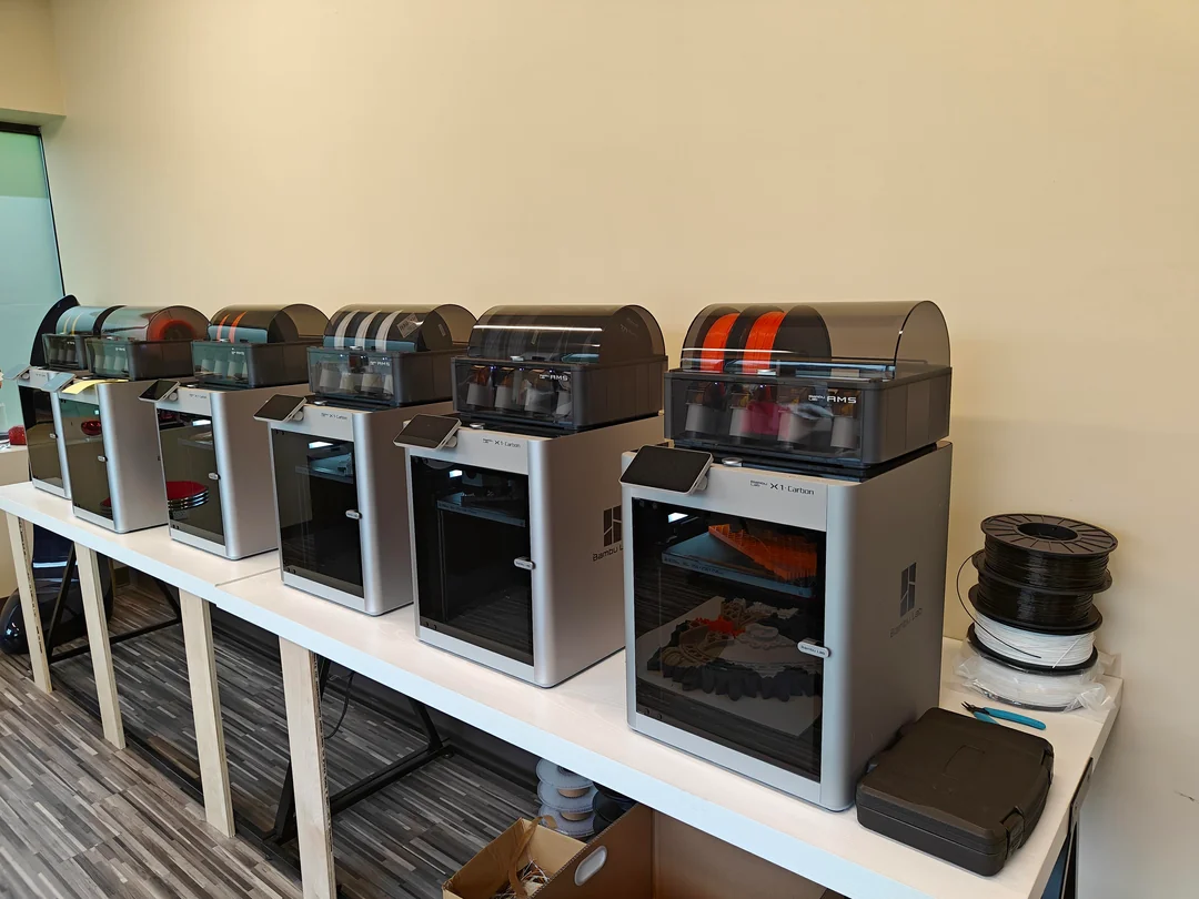
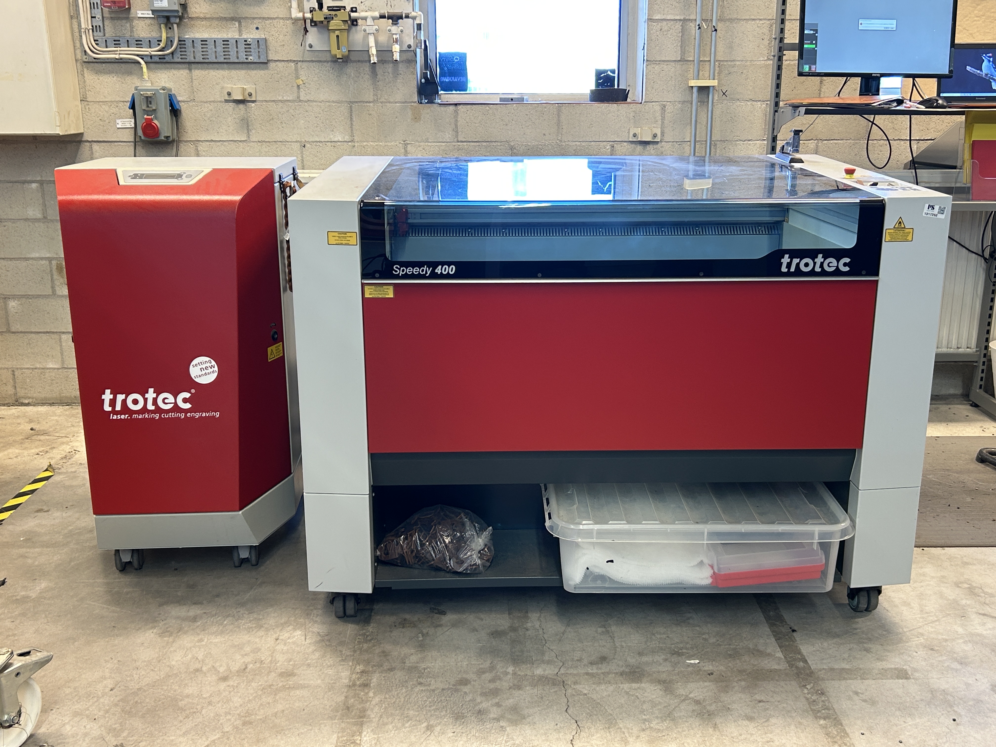
The entire design of Poly Plot was modeled in Fusion 360. The bed was fabricated from MDF using a Zünd digital cutter, while all 3D printed components were made from PETG on a Bambu Lab X1C printer. The black acrylic body panels, precisely cut using a Trotec Speedy 400 laser cutter, provide a clean enclosure for the mechanisms and wiring.
My Contributions
Designed the overall machine form and structure .
Conducted R&D of the ATC (Automatic Tool Changer) system .
Applied DFMA (Design for Manufacturing and Assembly) principles.
Managed manufacturing and fabrication of components.
Oversaw assembly and system integration of mechanical and electronic parts.
Prepared detailed documentation and project presentation for portfolio and exhibition.
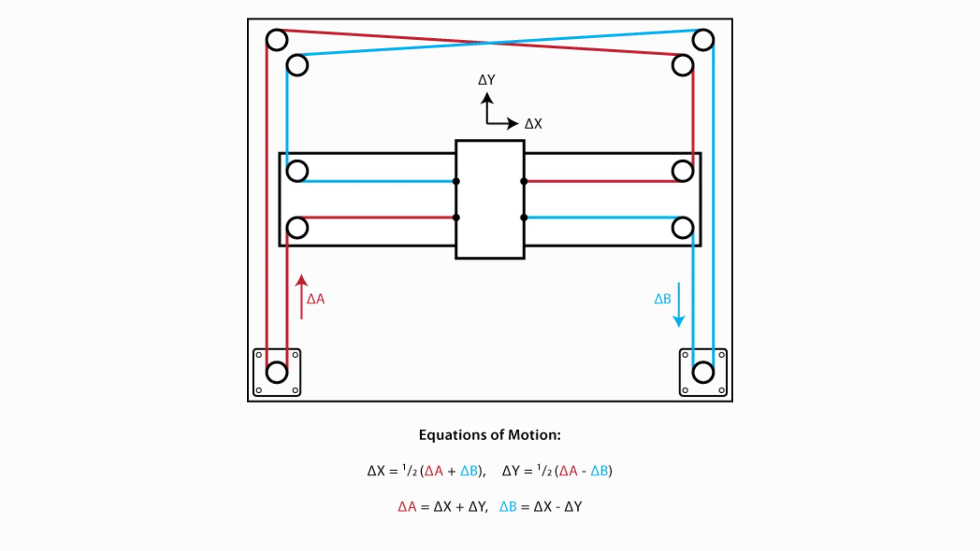
System Overview
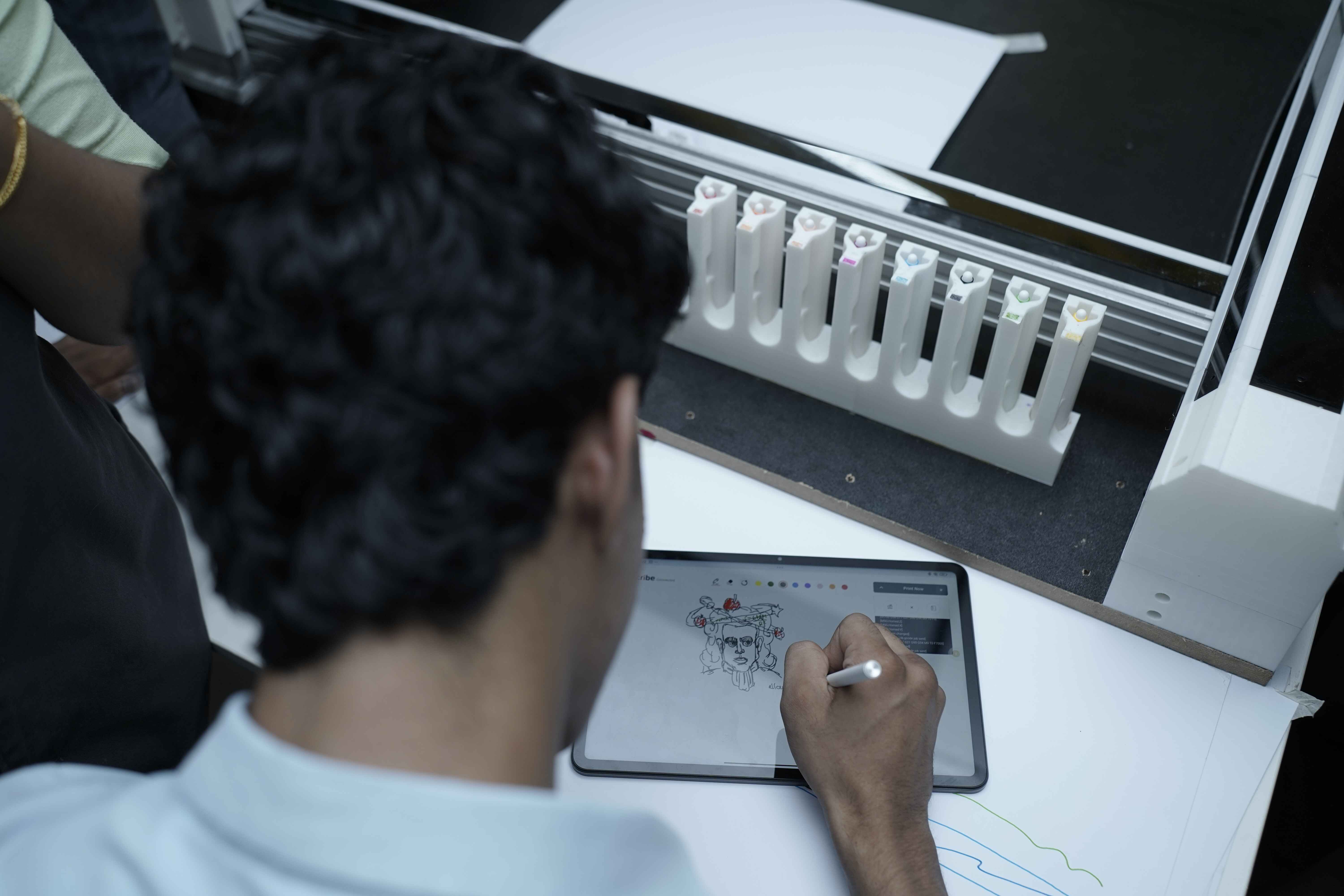
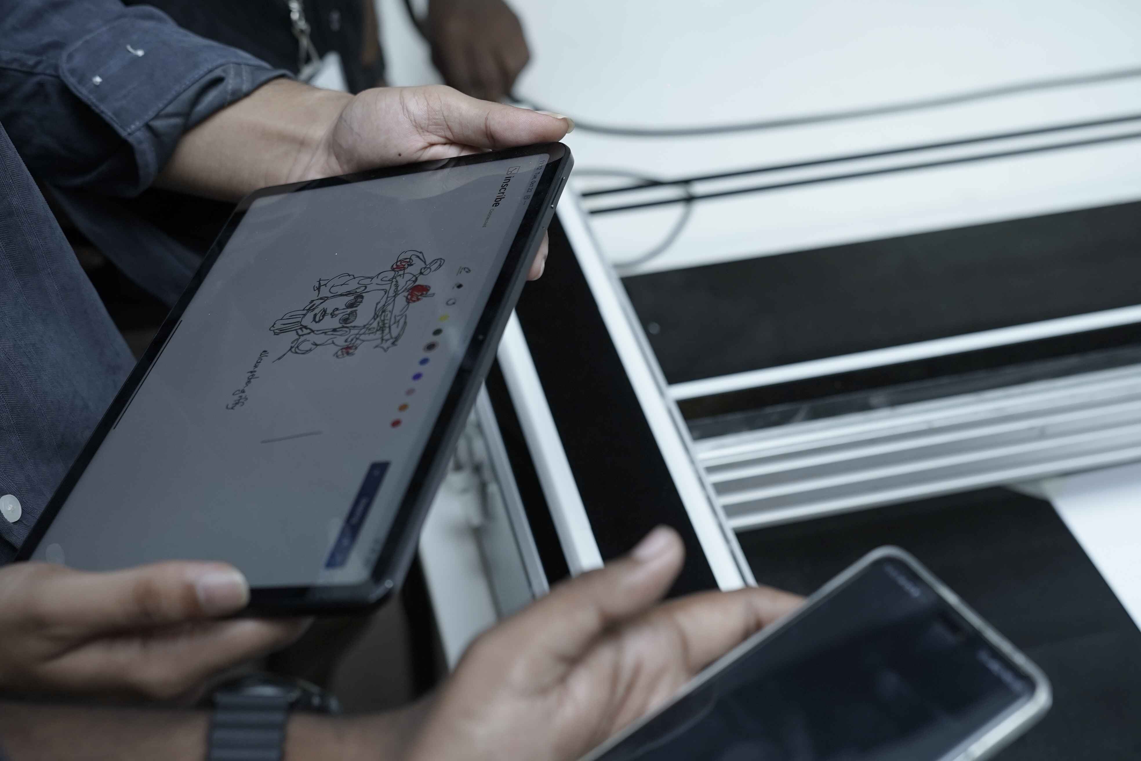
Functionality : The ATC mechanism enables the plotter to switch between 8 different pen colors without manual intervention, making the machine capable of executing multi-colored drawings and designs.
Design : The ATC mechanism is 3D printed and utilizes a magnetic docking system to securely attach and detach pens to the plotter's end effector.
Mechanism Design and Development
In this Plotter, mainly my tasks is to develop a automatic pen changing mechanism. The mechanism should to according to design for manufacturing (DFM) and design for assembly (DFA).
There are 4 mechanisms I need to design, which are listed below:
- Pen holder Module
- Docking Station
- End Effector
- Calibration Tool
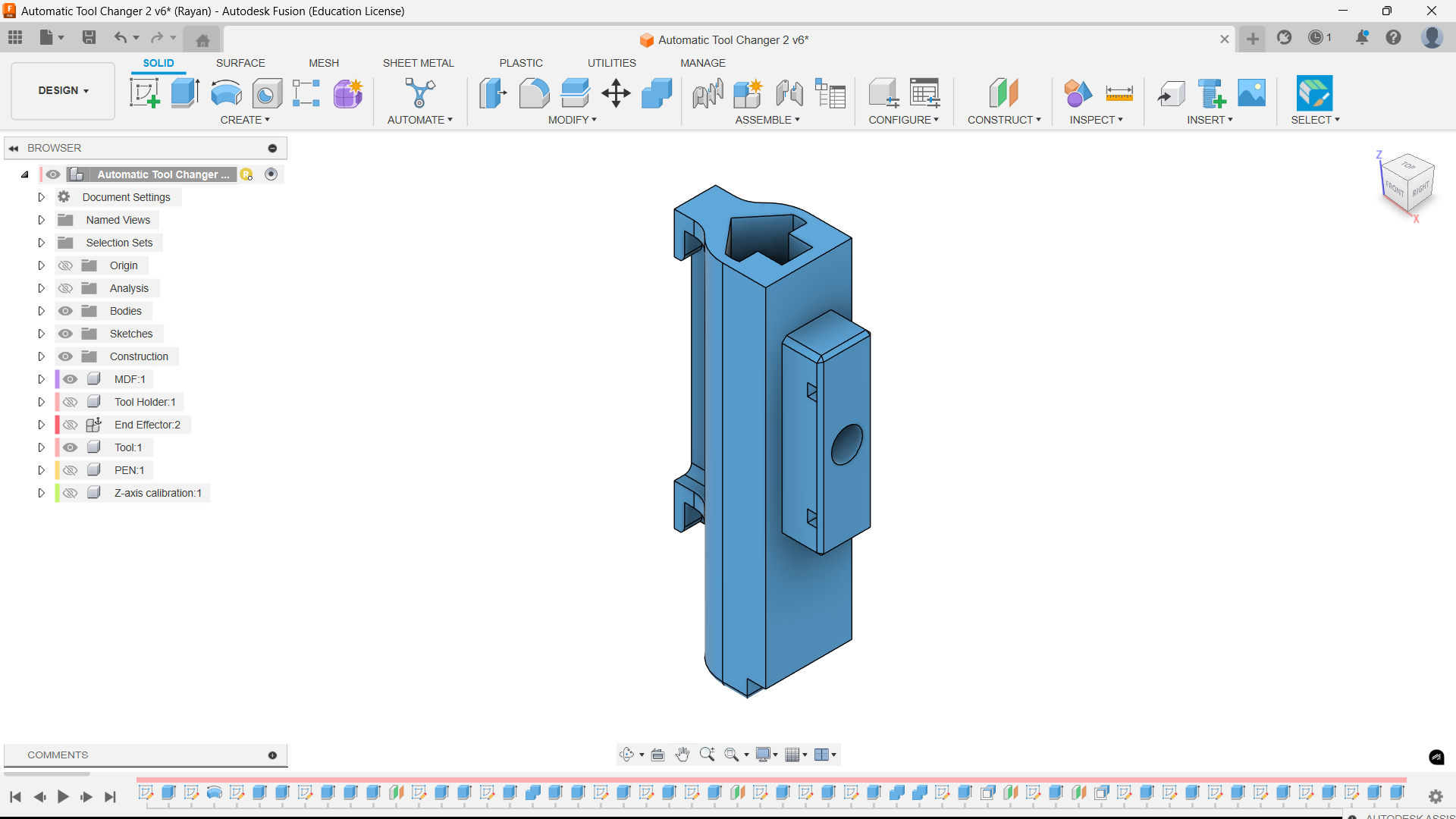
I used Fusion 360 for designing these mechanism.
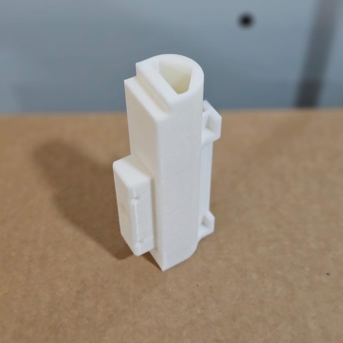
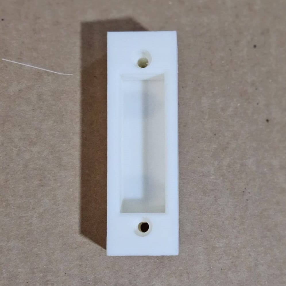
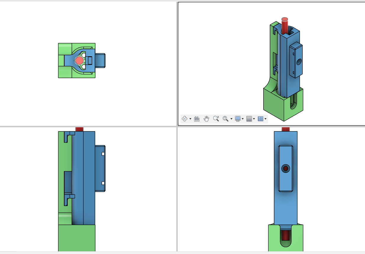
Magnetic Pen Holder Module
The magnetic coupling system uses strong magnets (10 mm diameter and 2.5 thickness) that ensure the tool is firmly held in place during operation and can be easily swapped when needed.
The magnets are strategically placed to prevent accidental detachment during movement.
The image below shows the design of the magnetic pen holder module.
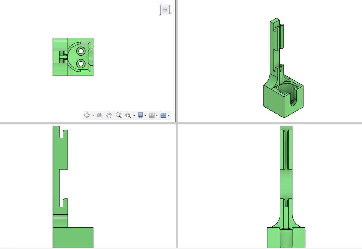
The image below shows multi view of the design of the magnetic pen holder module.
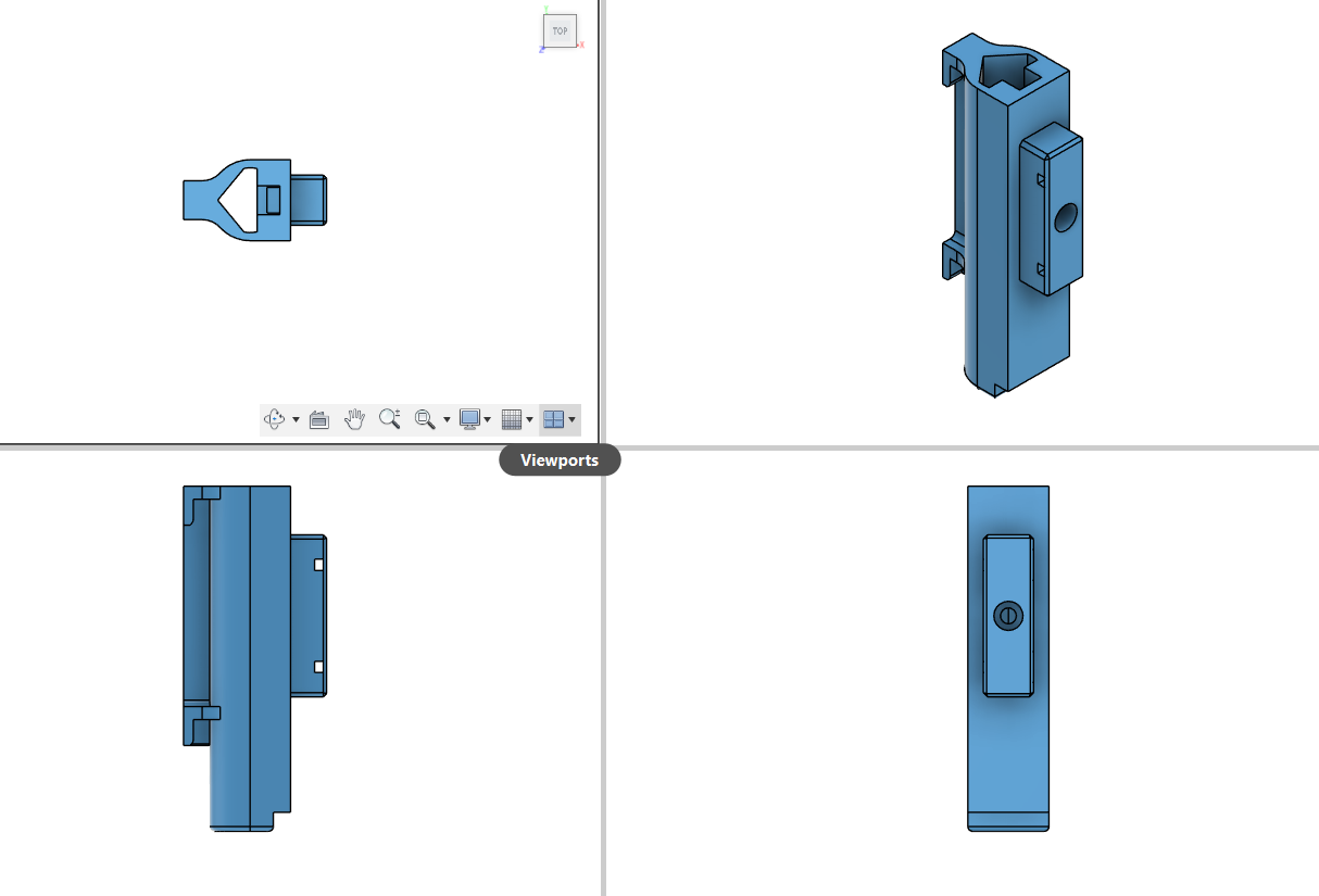
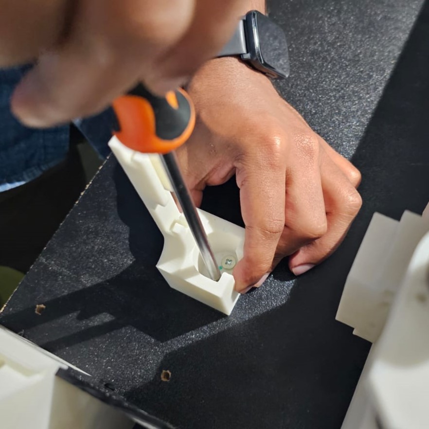
Once the design is verified, I decided to 3D print it. For the post-processing I used nose piler.
The image below illustrates the magnetic pen holder module. For functioning the module, I need two 10x2.5 mm disk magnet. and a M5 Bolt to tight the pen in the
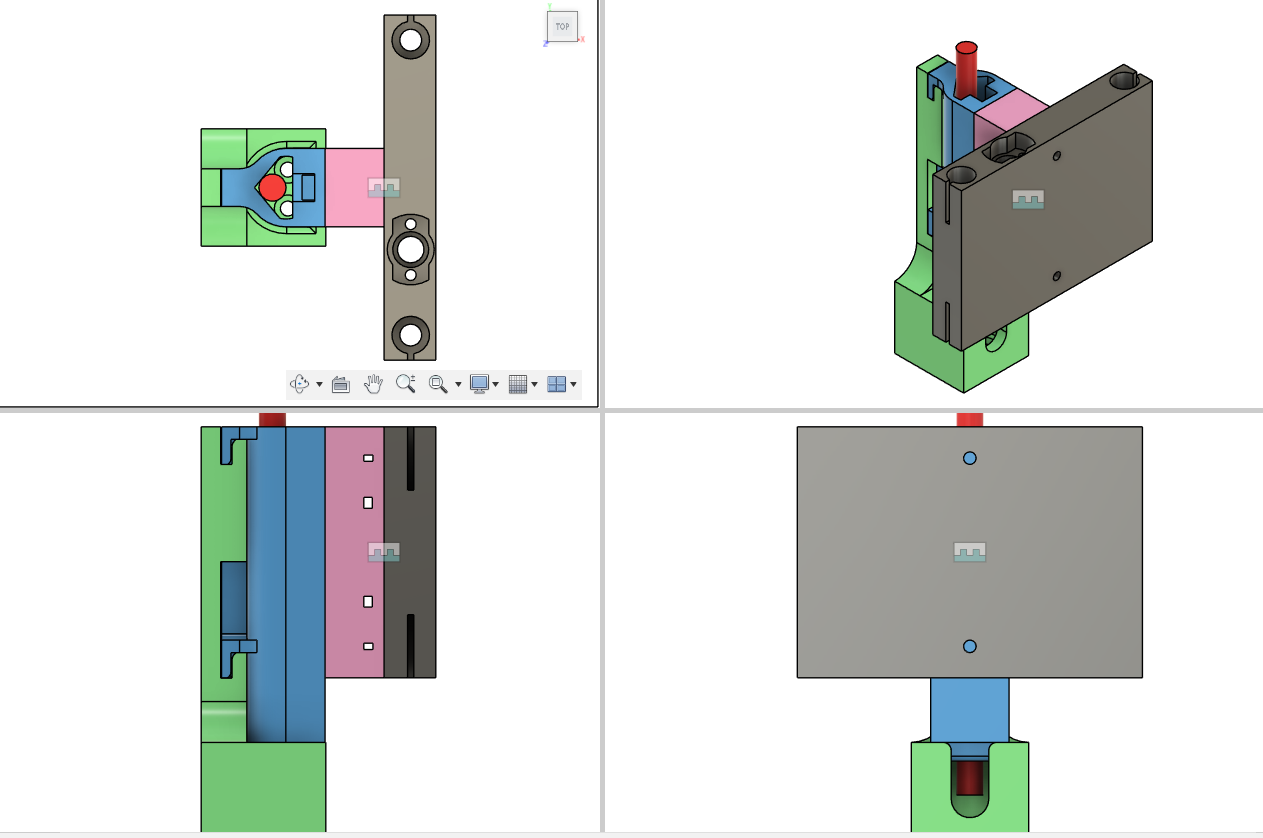
Docking Station
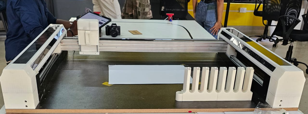
The docking station holds the pens in their respective positions, ready to be picked up by the end effector.
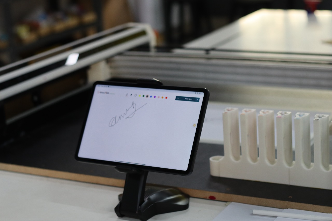
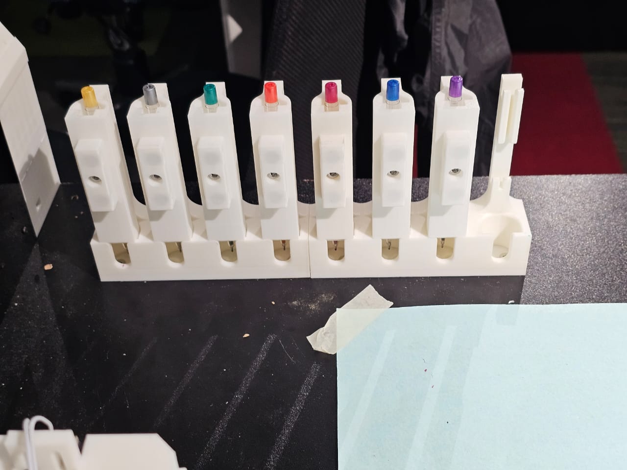
The station is designed to hold 8 different pens, each of a different color.
The magnetic system ensures that the pens stay in place until the end effector approaches to change the pen.
The image below depicts the multi view of the docking station.
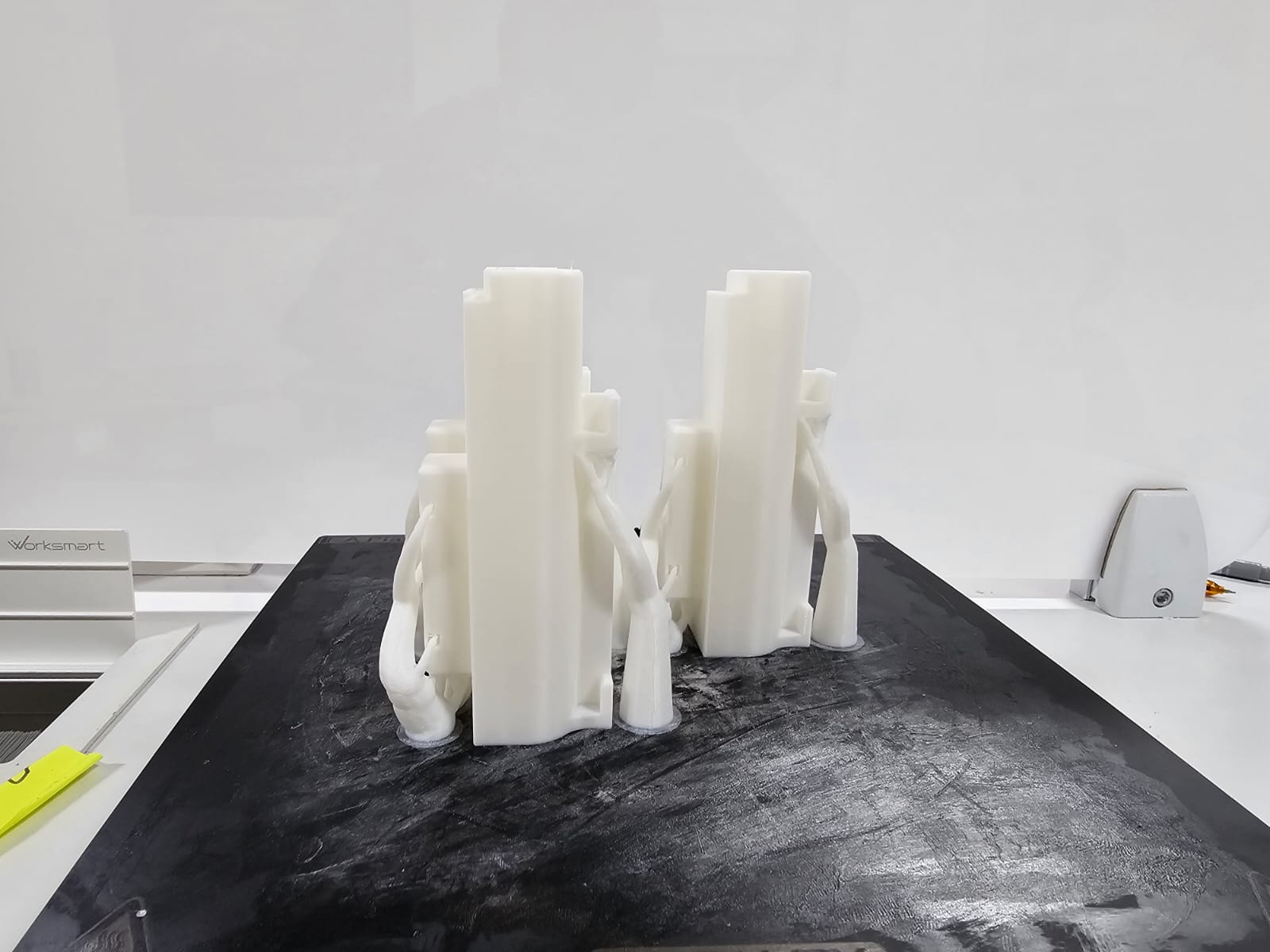
For the testing purpose, I decided to 3D print a single docking module. The test was succussful. However I increased the tolerence a bit for the smooth docking.
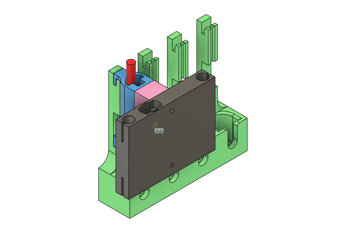
I cannot 3D print the entire docking station. So I decided to split it into half. That is 4 x 2. The image below shows the 3D printed 4 docking module.
Pen Height Calibration Tool
The calibration tool is used to adjust the height of each pen in the docking station to ensure that the pen tip is consistently at the correct distance from the paper.
The tool allows users to fine-tune the height of the pen, which is crucial for ensuring accurate pen pressure and consistent line thickness during plotting.
Calibration is simple: place the calibration tool beneath the pen, adjust the height, and confirm that the pen is properly aligned.
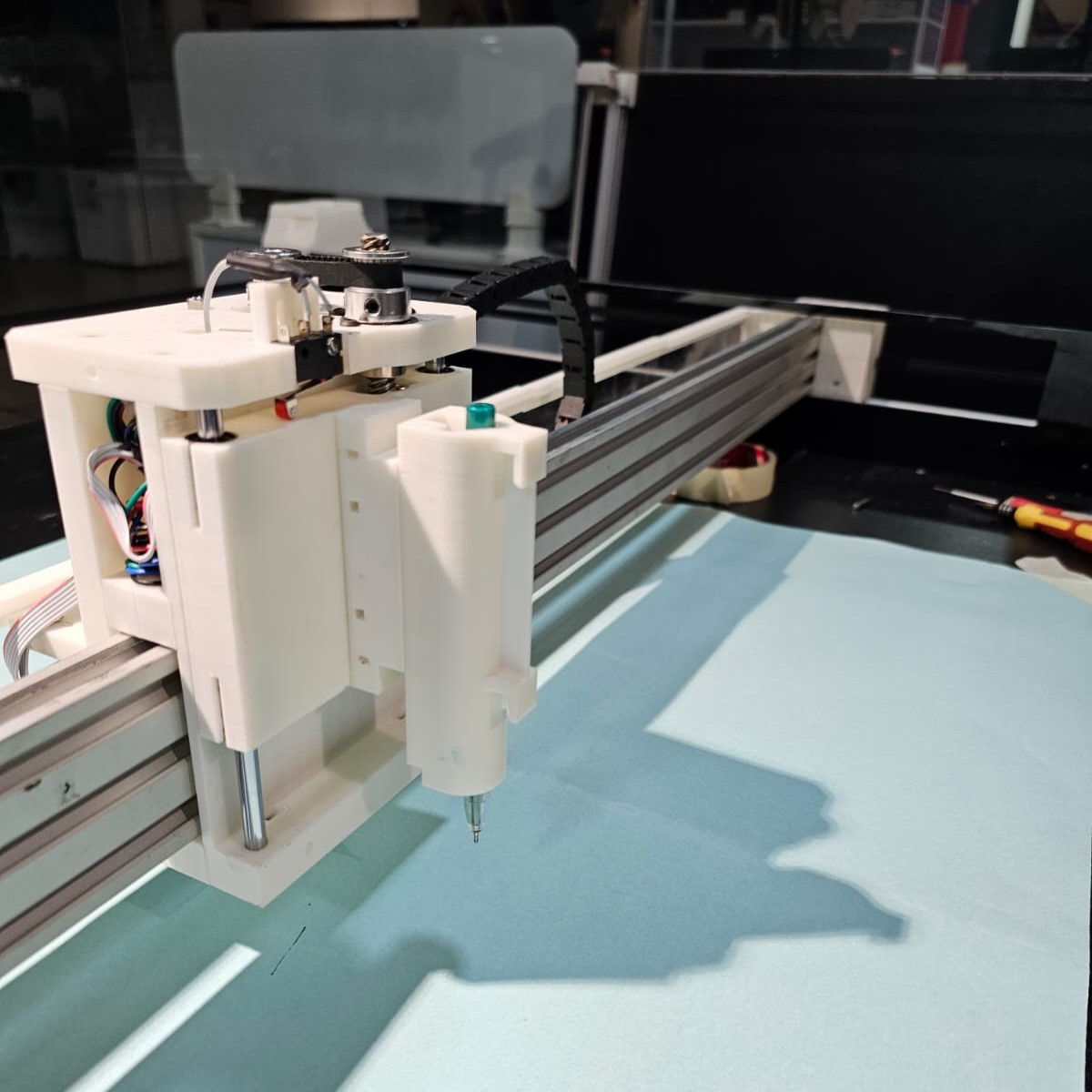
End Effector
The end effector of the plotter is equipped with a magnetic docking system that holds the pens in place during the plotting process.
When a tool change is required, the end effector moves to the docking station, where the magnetic system either releases the current pen or picks up a new one.
The end-effector is shown below. It consists of two 10mm x 2.5mm disk magnets.
Actuation and Control
The tool changer is controlled via the plotter’s main control system, which manages the movement of the end effector and ensures the correct pen is selected based on the drawing's design.
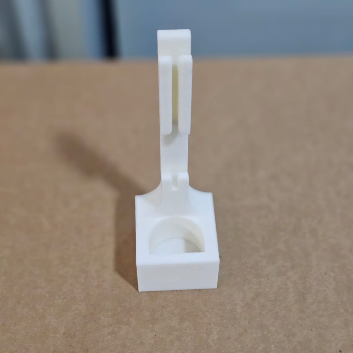
The image below shows the multi-view of the pen holder module with the docking module along with the pen.
The image below shows the multi-view of the assembled pen holder module, docking module, pen, and the end-effector.
The image below illustrates the entire design of the mechanism.
System Integration and Testing
For testing I decided to go with a single pen holder modukle and docking module. The magnetic attaching and detaching was checked and verified. Everything went smooth. The docking module was attached to the base mdf using a countersunk flat head screw.
Then the rest of the pen holding module and the docking station is fabricated, post-processed, and assembled for testing the entire system.
Check out the video below to watch the working of the ATC of the machine.
Check out the video below to watch the working of the ATC of the machine.
The image below illustrates the pen holdeing module is attached to the end-effector, which is attached to the z-axis.
The image below shows the pen modules resting in the docking station.

The entire Plotter is shown below.
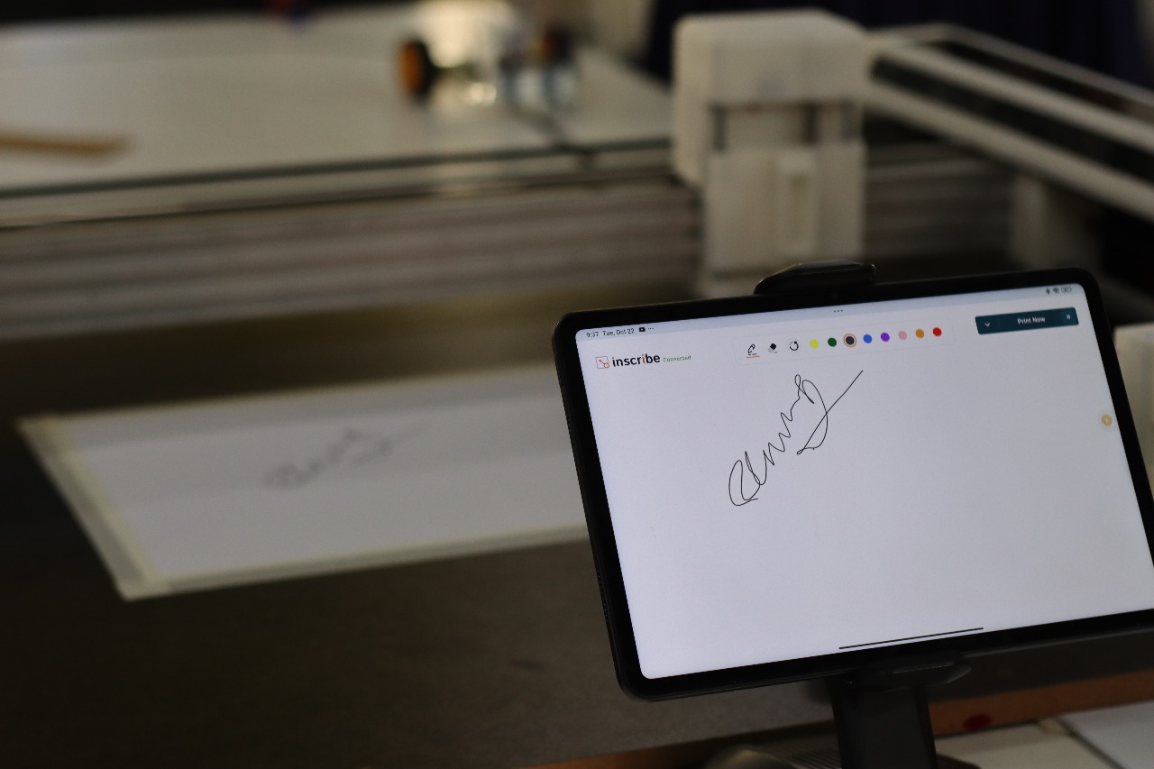
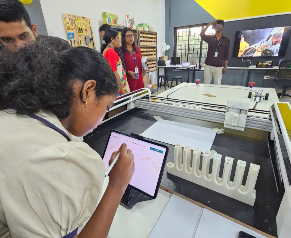
During the inauguration of the first Centre for Early Innovation Makerspace , we conducted the first user testing of the Poly Plot machine — allowing students and visitors to experience digital fabrication and automation firsthand
Future Scope
The ATC system, inspired by the Zund digital cutter, opens the door for future upgrades. In upcoming iterations, the pen modules can be replaced with interchangeable tools such as routers, cutters, laser engravers, or inkjet printing heads. This enhancement will transform Poly Plot from a plotting machine into a multi-functional digital fabrication platform, bringing advanced fabrication capabilities directly to school makerspaces and empowering students to explore hands-on innovation at a whole new level.