Table of Contents
Project Overview
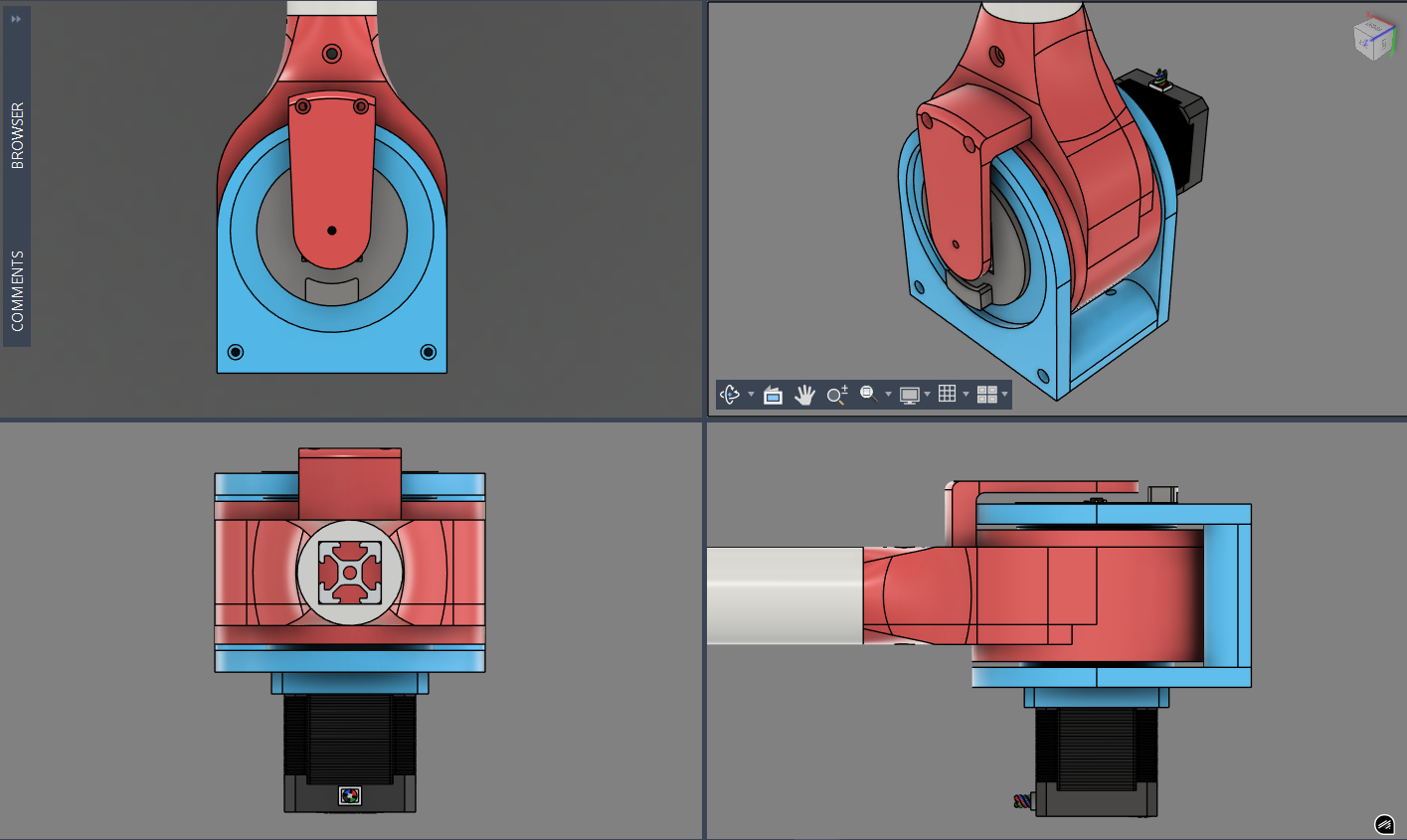
This document details a precision 21:1 cycloidal drive mechanism designed in Fusion 360, built with 3D-printed PETG, actuated by a NEMA17 stepper motor, and controlled by an ESP32 running custom Arduino firmware.
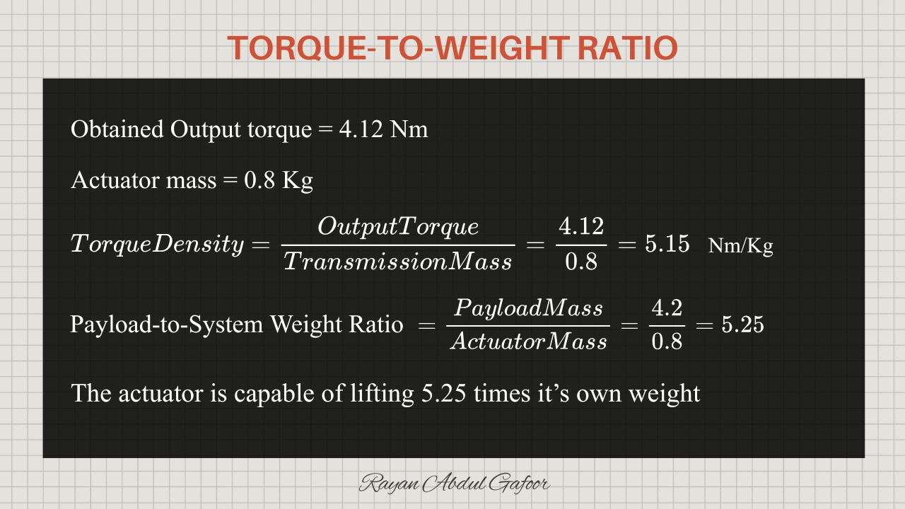
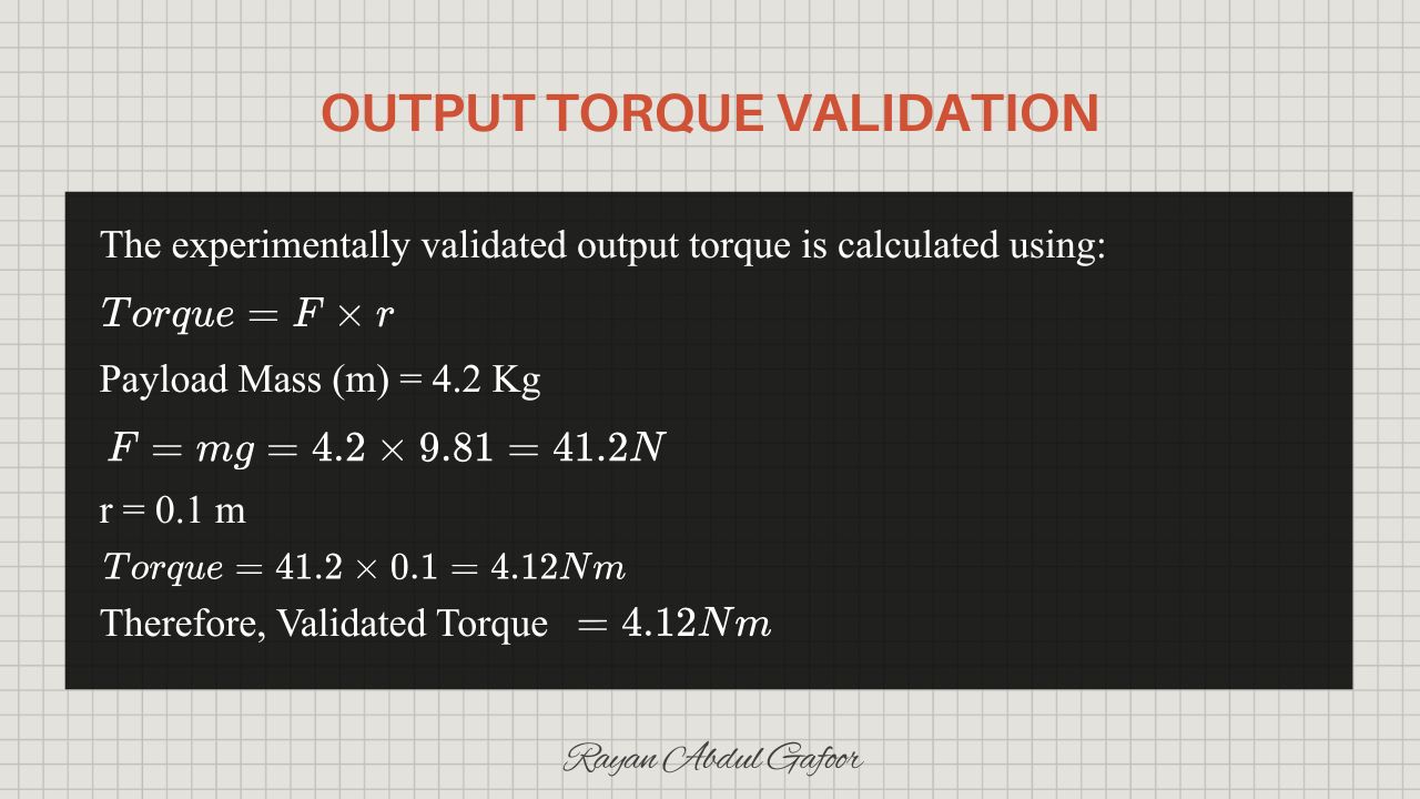
- Designed a 21:1 reverse-cycloidal actuator optimized for additive manufacturability, achieving 4.12 Nm validated output torque and 0.0053 degree angular resolution through the integration of a NEMA17 stepper motor, TB6600 driver, AS5600 absolute encoder, and custom ESP32 firmware for articulated robotic joints.
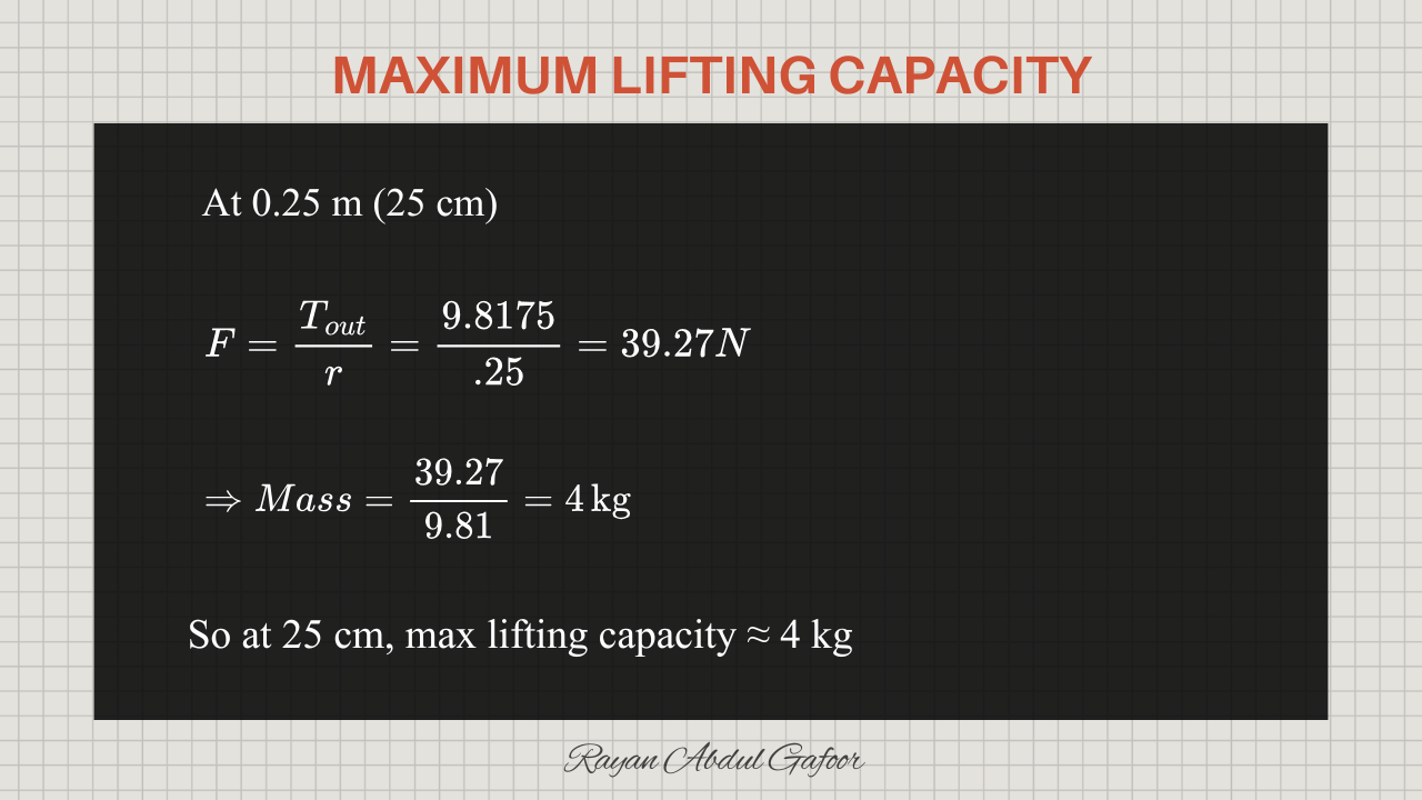
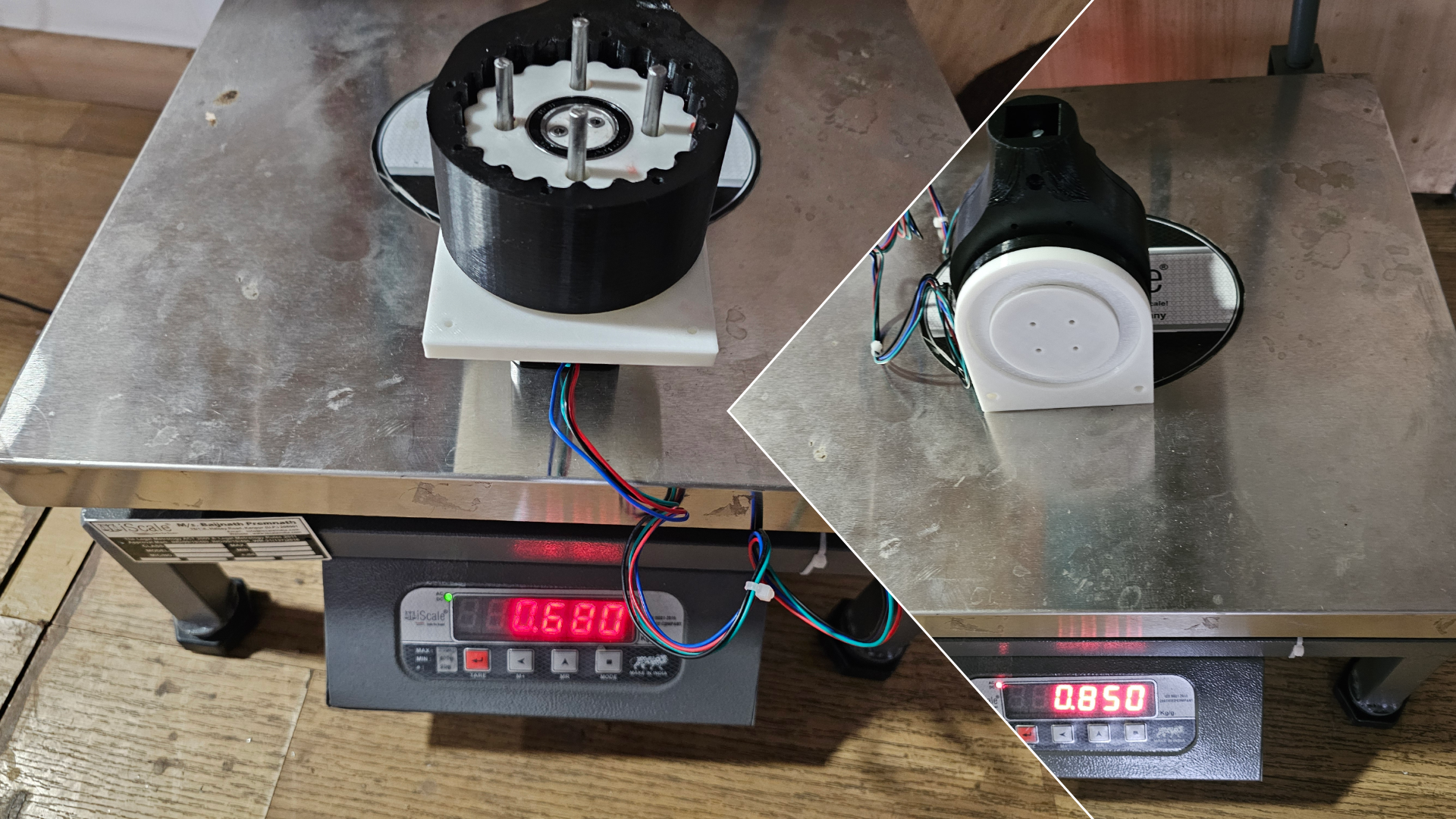
- Optimized 10+ interdependent geometric parameters including roller count, eccentricity, lobe profile, and operating clearances to develop a lightweight 0.8 kg PETG transmission capable of lifting a 4.2 kg payload at 10 cm reach.
- Achieved a 5.15 Nm/kg torque-to-weight ratio by minimizing transmission mass, resulting in a compact robotic joint module capable of lifting 5.25 times its own weight.
- Eliminated kinematic chain offsets by designing a coaxial reverse-cycloidal joint architecture in Fusion 360, simplifying forward/inverse kinematics, Jacobian computation, and manipulator dynamic modeling.
Design Goals & Constraints
High reduction ratio (21:1) for strong torque multiplication
3D printability using PETG for rapid prototyping and cost-effectiveness
Minimal mechanical backlash through fit and pin/bearing tolerances
Direct stepper motor drive, controllable by custom firmware
Follow the design for the manufacturing and assembly (DFMA) principle.
Simple assembly using standard bearings, nuts, and bolts
Transmission Mechanisms
Transmission mechanisms are the system that transmits, modifies, or transforms that motion.
Passively transmits energy from actuator to output.
Modifies speed, torque, direction, or type of motion.
Cycloidal Drive
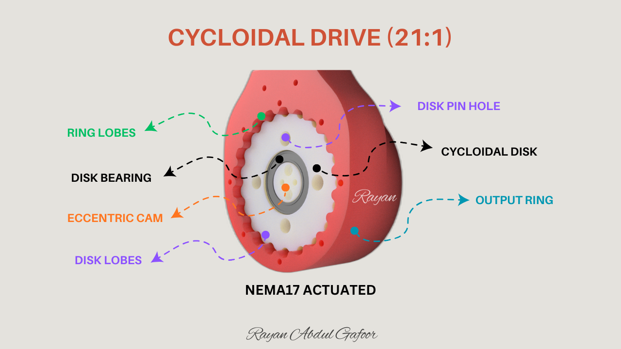
A cycloidal drive uses an eccentric cam to rotate a lobed cycloidal disc inside a circular array of rollers or pins. As the cycloidal disc rotates, it "walks" around the stationary outer ring, causing differential motion transferred to the output shaft via output pins or followers.
Main Parts:
- Eccentric cam (offsets disc center from input shaft)
- Cycloidal disc (lobed plate with cycloidal profile)
- Ring/pin array (stationary which holds pins or rollers)
- Output shaft (connected to output pins following the disc)
- Return pins/bearings (reduce friction, guide output)
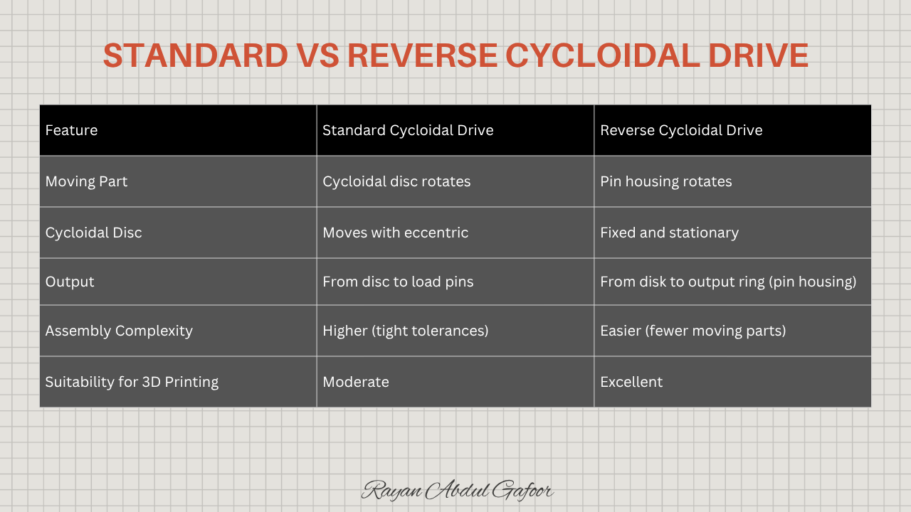
Reverse Cycloidal Drive
A reverse cycloidal drive is a compact, high-torque speed reducer in which the cycloidal disc remains stationary and the output pin housing rotates, producing mechanical advantage through eccentric motion and rolling contact.
I developed this cycloidal drive for use in my serial robotic manipulator, and I specifically chose the reverse cycloidal drive because it keeps the drives output perfectly coaxial with the robot’s joint axis. This eliminates any physical offset between the drive and the link, ensuring that the joint geometry remains clean and centered.
A standard (normal) cycloidal drive typically introduces an offset between the gearbox center and the link center, which adds an extra rigid translation to the robot’s kinematic chain. Such an offset must then be explicitly included in all mathematical models forward kinematics, inverse kinematics, jacobian calculations, and dynamic equations, to maintain accuracy.
By using a reverse cycloidal drive, I avoid these unnecessary geometric complications, maintain a coaxial joint layout, and ensure simpler, more robust kinematic modelling for the manipulator.
Working Principle
A motor drives an eccentric shaft that orbits inside a stationary cycloidal disc.
Instead of the cycloidal disc rotating, the pin housing (or output ring) follows the orbital path.
As the eccentric rotates, each lobe of the disc sequentially engages the surrounding pins, causing the output ring to rotate smoothly.
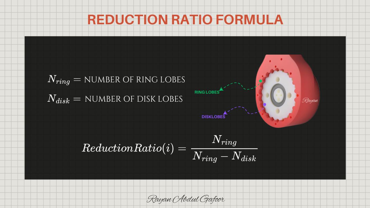
The reduction ratio is generated by the difference between the number of pins and cycloidal lobes, following the same mathematical relationship as a normal cycloidal drive.
The motion is transmitted through rolling contact, giving the drive high efficiency and smooth torque output.
Advantages of the Reverse Cycloidal
More stable load path and easier assembly
Output remains coaxial with the motor shaft
Easier integration into serial manipulator joints
Lower backlash due to fixed geometry and rigid center plate.
Compact and easy to integrate into robotic joints using NEMA17 motors.
Reduction Ratio
Kinematic Behavior
The eccentric shaft causes a perfect cycloidal motion path around the fixed disc.
Each rotation of the eccentric advances the output ring by 1 pin step.
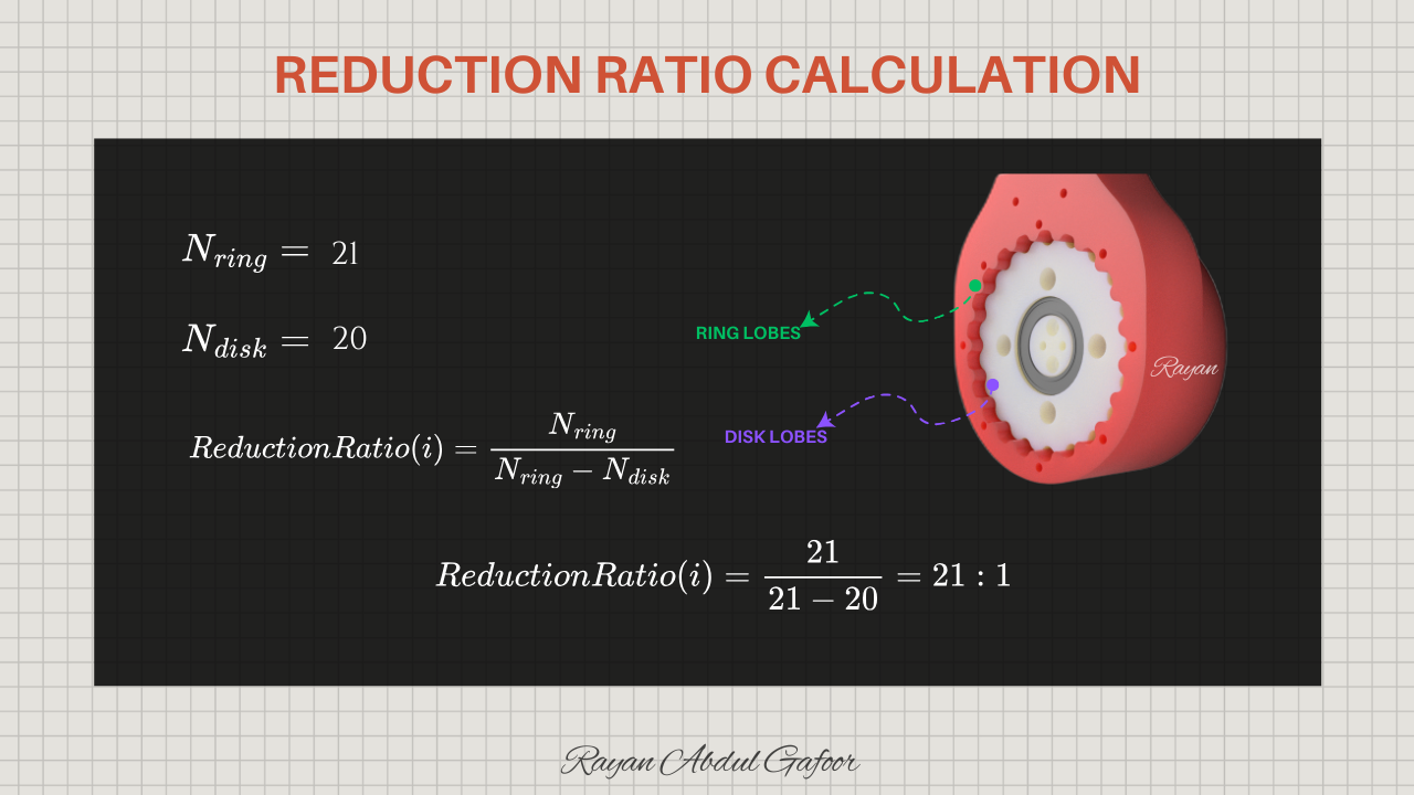
After one full motor rotation, the output rotates only 1/21 of a turn (for 21:1), creating the reduction.
Load is distributed across many lobes simultaneously, improving torque and reducing wear.
The motion of the reverse cycloidal drive is smoother at low speeds because the fixed disc acts as a rigid guide.
Dynamic Characteristics
Rolling contact between the lobes and pins produces high torque-density.
The fixed cycloid plate absorbs eccentric forces, reducing bearing vibration.
Radial forces from the eccentric motion are transferred mainly to the output ring bearings.
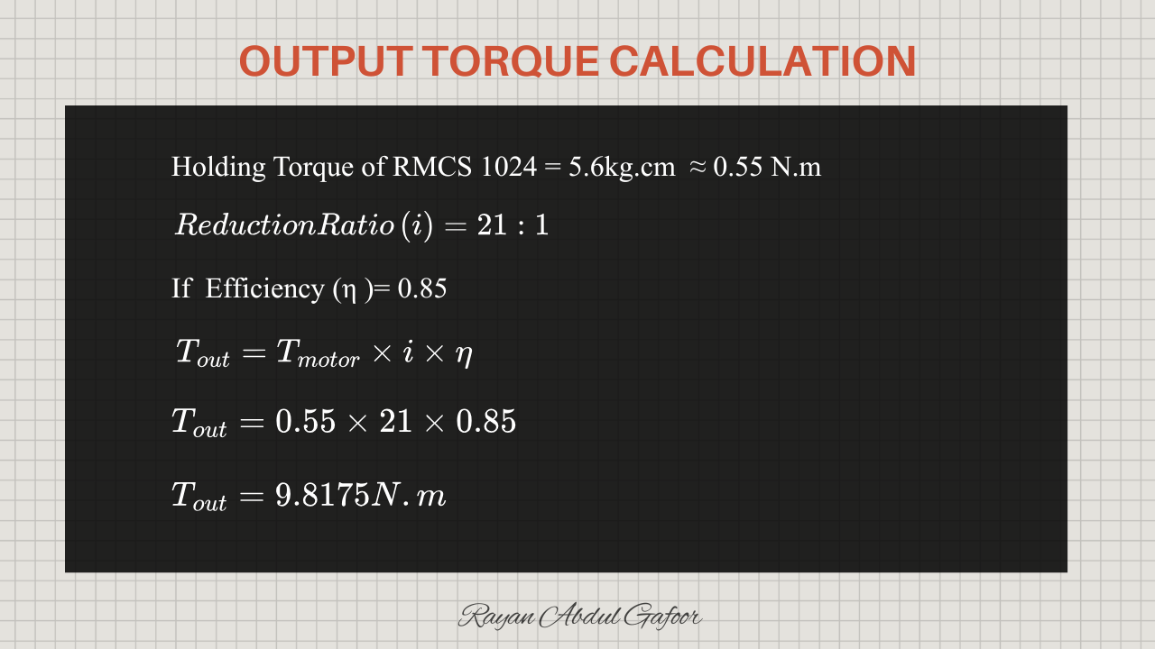
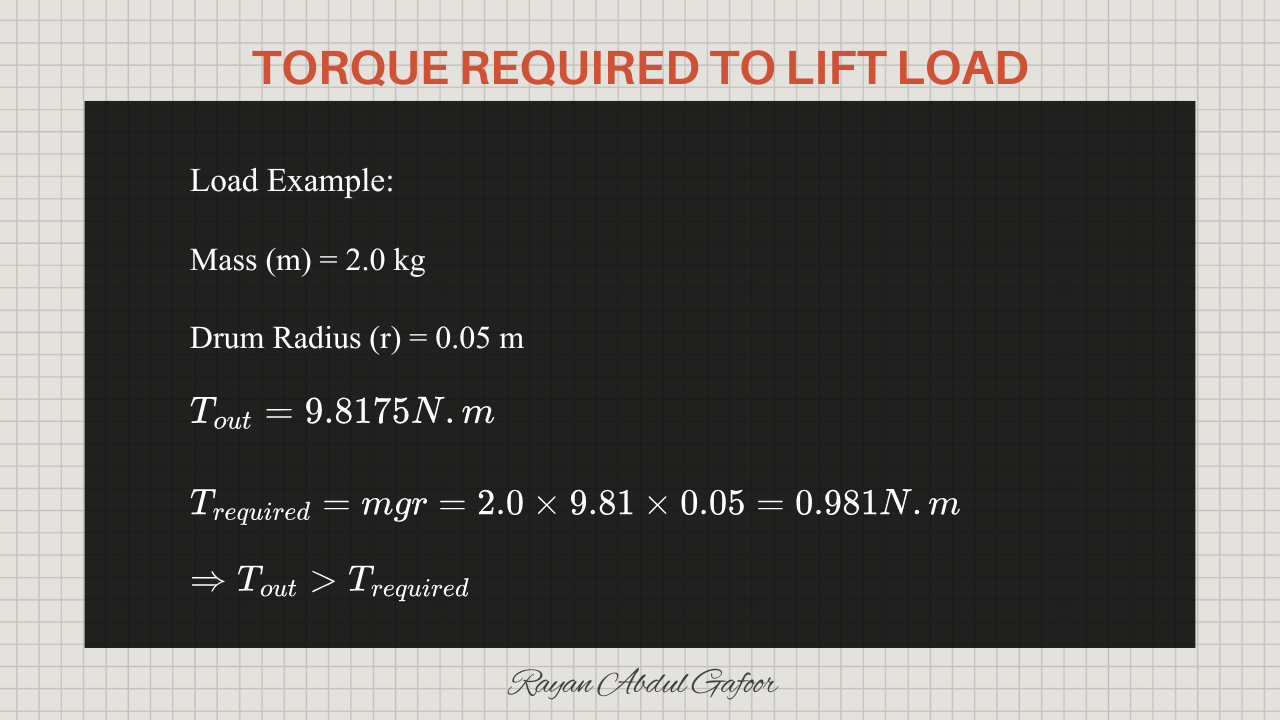
Calculations
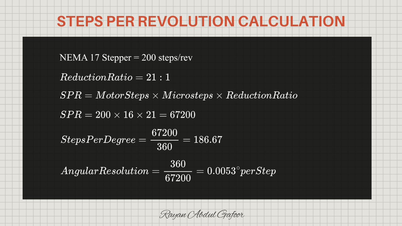
Designing
The design process of this cycloidal drive involves carefully selecting and refining several geometric and mechanical parameters such as the number of rollers, number of cycloidal lobes, pitch-circle diameter, roller diameter, eccentricity, base circle diameter, hole dimensions on the cycloidal disk, clearances for smooth motion, thickness of the cycloidal plate, and the output pin layout.
Each of these factors influences the motion profile, load distribution, efficiency, and overall behavior of the drive, and their relationships require multiple interconnected calculations to determine the correct proportions, spacing, and geometry.
Through iterative adjustments guided by these calculations, the design is tuned to achieve the desired reduction ratio, torque capacity, smooth operation, and compact form.
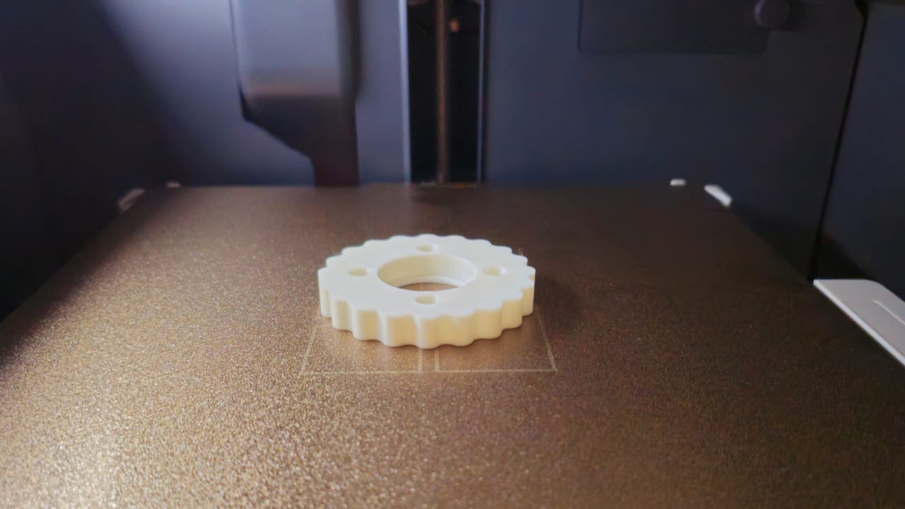
The final geometry is optimized for strength, reliability, and manufacturability, ensuring that the PETG-printed drive performs effectively as a robotic joint actuator.
Digital Fabrication
All components were 3D printed on a Bambu Lab P1S using black and white PETG. The print configuration included 5 wall loops for increased strength and rigidity, and a 50% infill density to ensure optimal structural integrity under load.
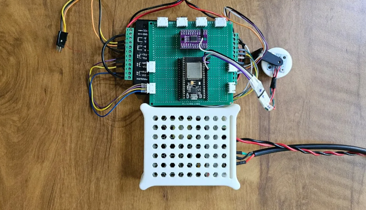
Hardware Overview
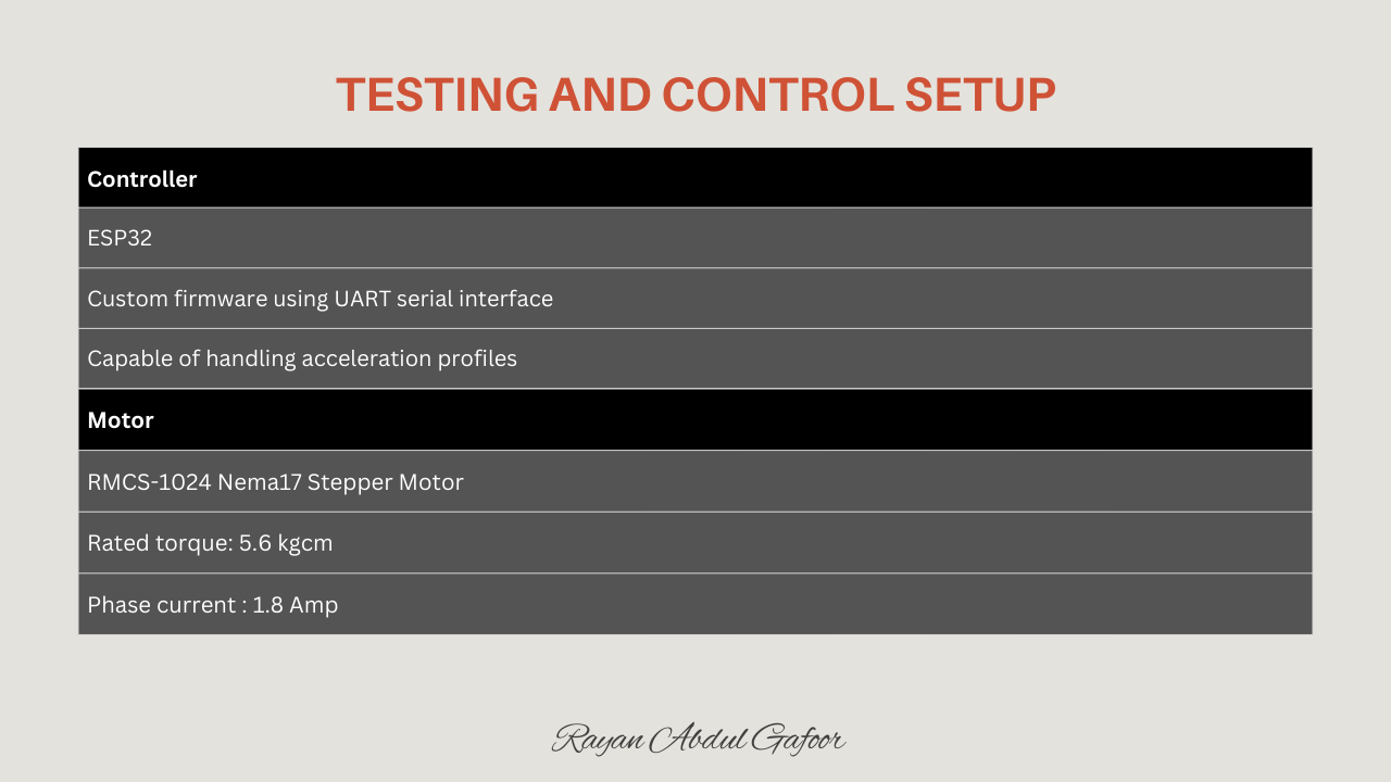
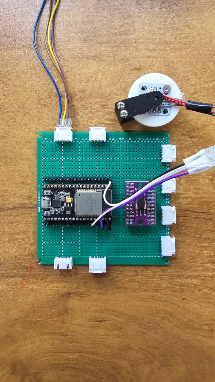
Controller
- ESP32
- Custom firmware using UART serial interface
- Capable of handling acceleration profiles and fast control loops
Motor
- RMCS-1024 Nema17 Stepper Motor
- Rated torque: 5.6 kgcm
- Phase current : 1.8 Amp
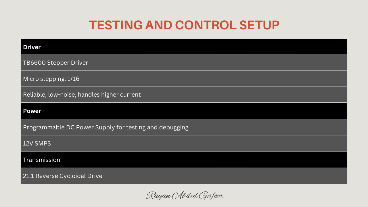
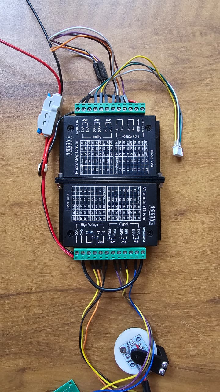
Driver
- TB6600 Stepper Driver
- Micro stepping: 1/16
- Reliable, low-noise, handles higher current
Power
- Programmable DC Power Supply for testing and debugging then used SMPS
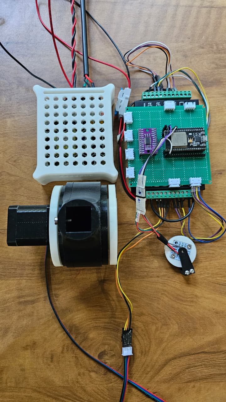
Transmission
- 21:1 Reverse Cycloidal Drive
- 3D printed in PETG using Bambu Lab P1S
- Lightweight + durable
- Naturally back-drivable, allowing safer human-robot interaction
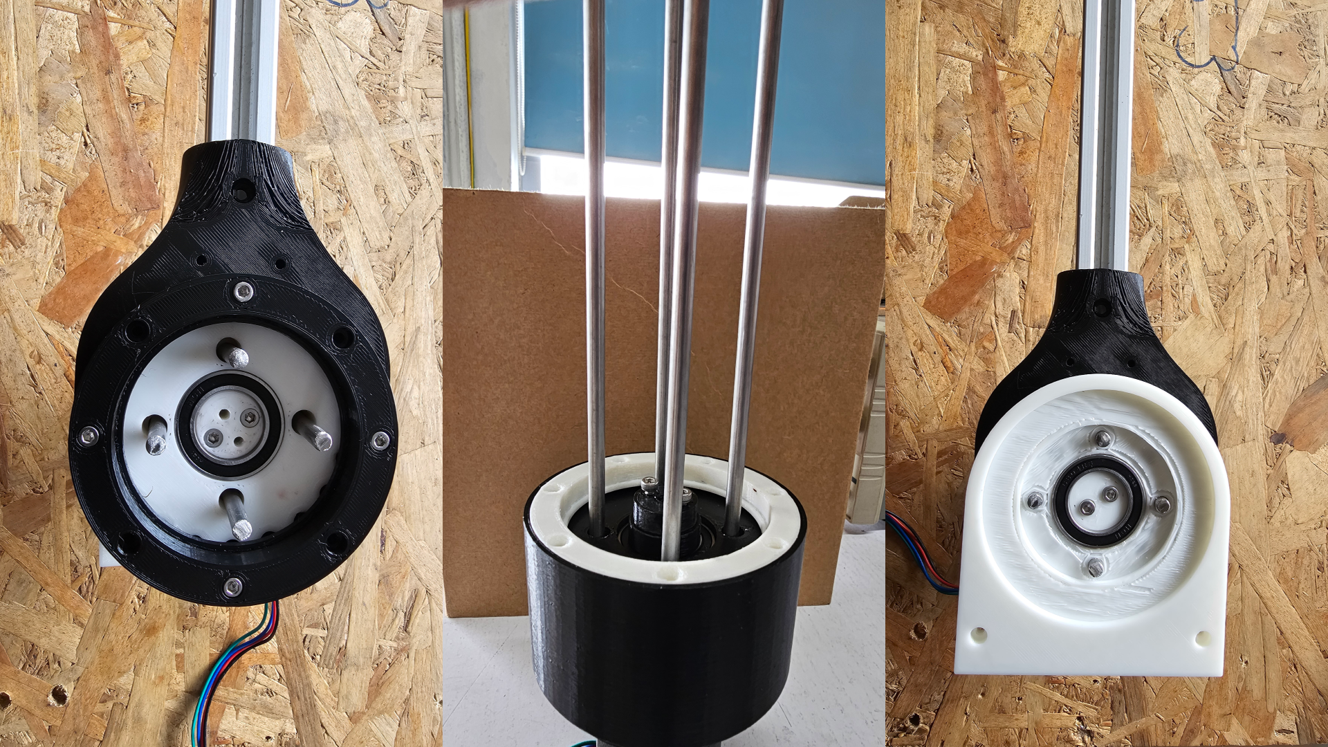
Assembly
For lubrication, I used Shell Gadus S3 red grease to ensure smooth operation, reduce friction between the cycloidal lobes and rollers, and minimize wear during extended use.

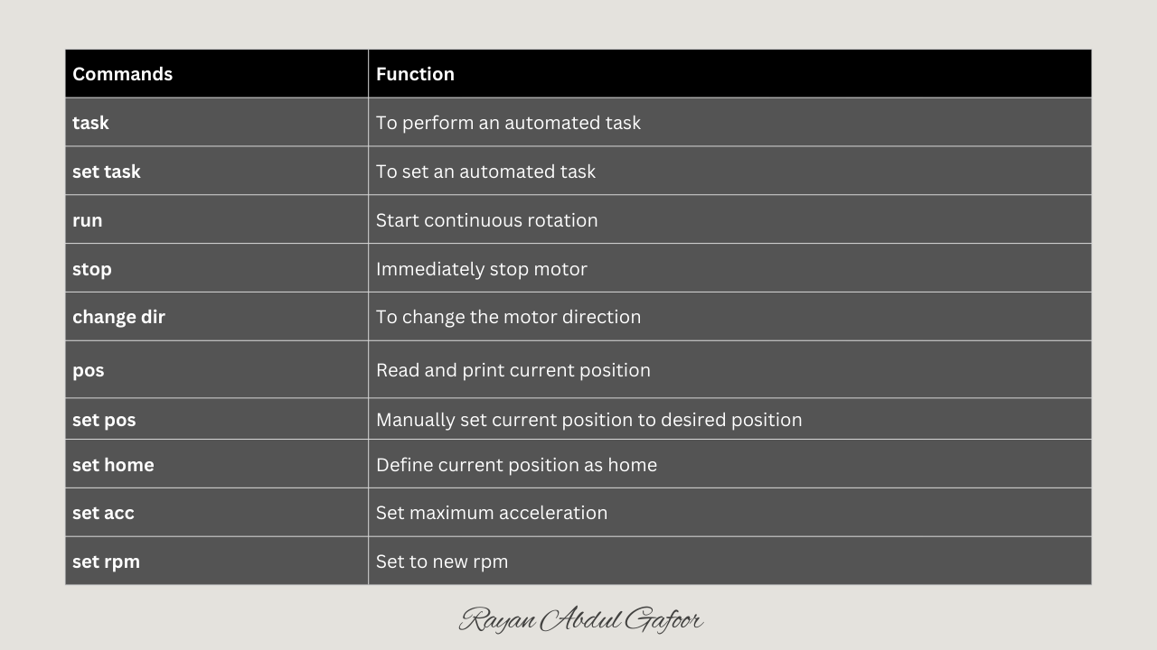
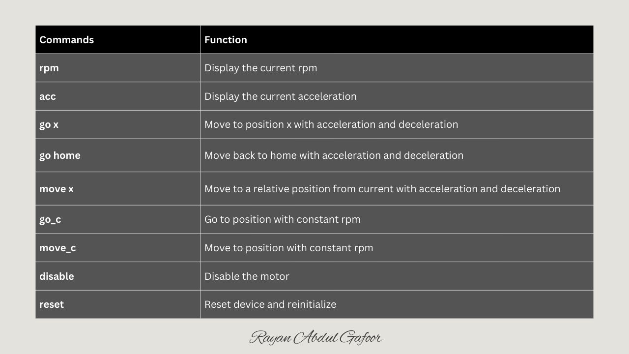
Custom Firmware
I wrote a custom serial-command firmware that allows complete control of the cycloidal actuator.
Testing the Drive
Payload Testing
Cycloidal Drives in Robots
Cycloidal drives are widely used in robotic joints because they offer high torque in a compact and lightweight design.
Their low backlash enables precise and repeatable motion, which is essential for accurate robotic positioning.
The high shock-load resistance of cycloidal drives protects robot joints from sudden impacts during movement or collisions.
Their smooth low-speed performance makes them ideal for tasks requiring slow, controlled, and stable robotic motion.
They allow robots to carry heavier payloads without increasing the size or weight of the actuator.
The high reduction ratios achievable with cycloidal drives enable small motors like NEMA17 or NEMA23 to deliver large output torques.
Robots benefit from the reduced vibration of cycloidal drives, resulting in smoother trajectories and improved control accuracy.
Cycloidal drives maintain performance even under repeated directional changes, making them ideal for dynamic robotic applications.
Advantages of Cycloidal Drive
Back-drivable, Smooth and quiet at medium speeds, High torque-to-size ratio, easy integration into multi-DOF kinematics.
They offer high torque density because multiple lobes share the load simultaneously.
They can withstand extremely high shock loads, often up to five times the rated torque.
Cycloidal drives have naturally low backlash due to their geometry and load distribution.
They deliver smooth and precise motion even at very low speeds.
Their rolling motion helps absorb vibration and reduce resonance.
Cycloidal mechanisms are reliable and durable because their load is distributed over many contact points.
Limitations of Cycloidal Drive
Cycloidal drives are harder to manufacture because they require precise geometry and tight tolerances.
Their design involves complex kinematic and geometric calculations that are harder than spur or planetary systems.
The eccentric motion creates high radial loads on bearings, requiring strong and well-aligned bearing support.
They are difficult to back-drive due to high reduction ratios and friction.
They require lubrication to prevent wear and ensure smooth operation.