Table of Contents
Transmission Mechanisms
Transmission mechanisms are the system that transmits, modifies, or transforms that motion.
Passively transmits energy from actuator to output.
Modifies speed, torque, direction, or type of motion.
What is a Harmonic Drive?
A harmonic drive also called a strain wave gear is a type of mechanical speed reducer known for its:
- High gear reduction ratio in a very compact size
- Zero or near-zero backlash
- Exceptional positioning accuracy
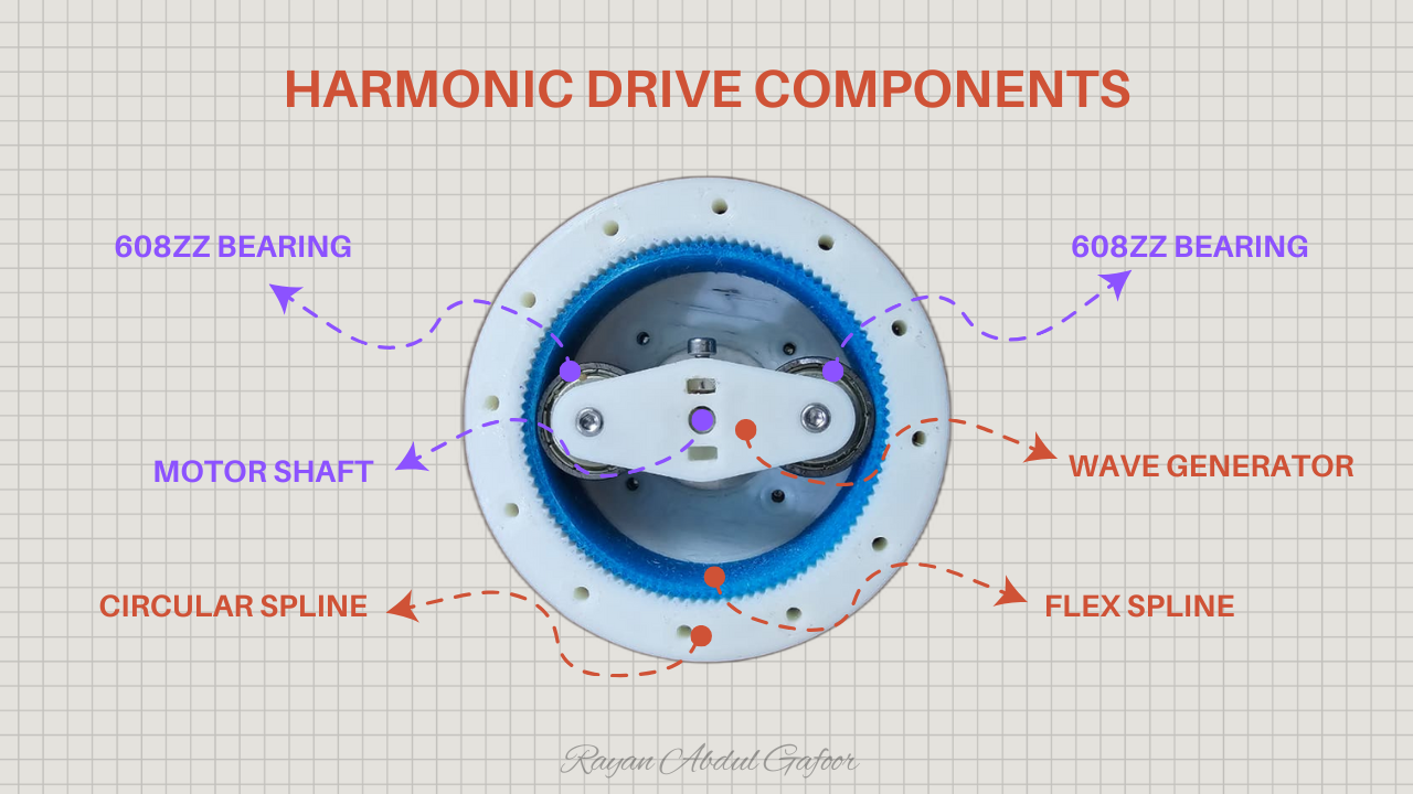
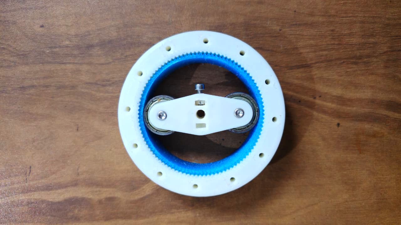
It consists of three main components:
- Wave Generator: an elliptical cam (usually attached to the input shaft).
- Flex spline: a thin, flexible cup with external teeth.
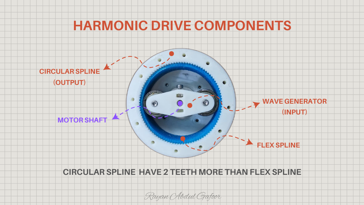
- Circular Spline: a rigid ring with internal teeth (slightly more teeth than the flex spline).
This harmonic drive I built uses a 50:1 reduction ratio , meaning one full motor rotation produces slow, controlled, and powerful output.
How It Works
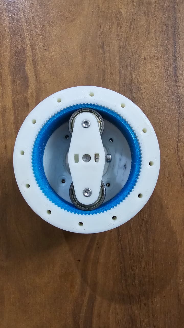
- The base shaft turns the strain wave generator, which is elliptical with bearings around the circumference. The bearings allow the strain wave generator to rotate within the elliptical gear (flex spline).
- The wave generator deforms the flex spline into an elliptical shape so that its teeth engage the circular spline at two opposite points.
- When the wave generator rotates, the elliptical deformation “waves” around the circular spline.
- Since the flex spline has fewer teeth, each full rotation of the wave generator causes the flex spline to move slightly because of the difference in tooth count.
- The output therefore rotates very slowly and with high torque, producing a large reduction ratio.
Circular Spline (output) have 2 teeth more than flex spline.
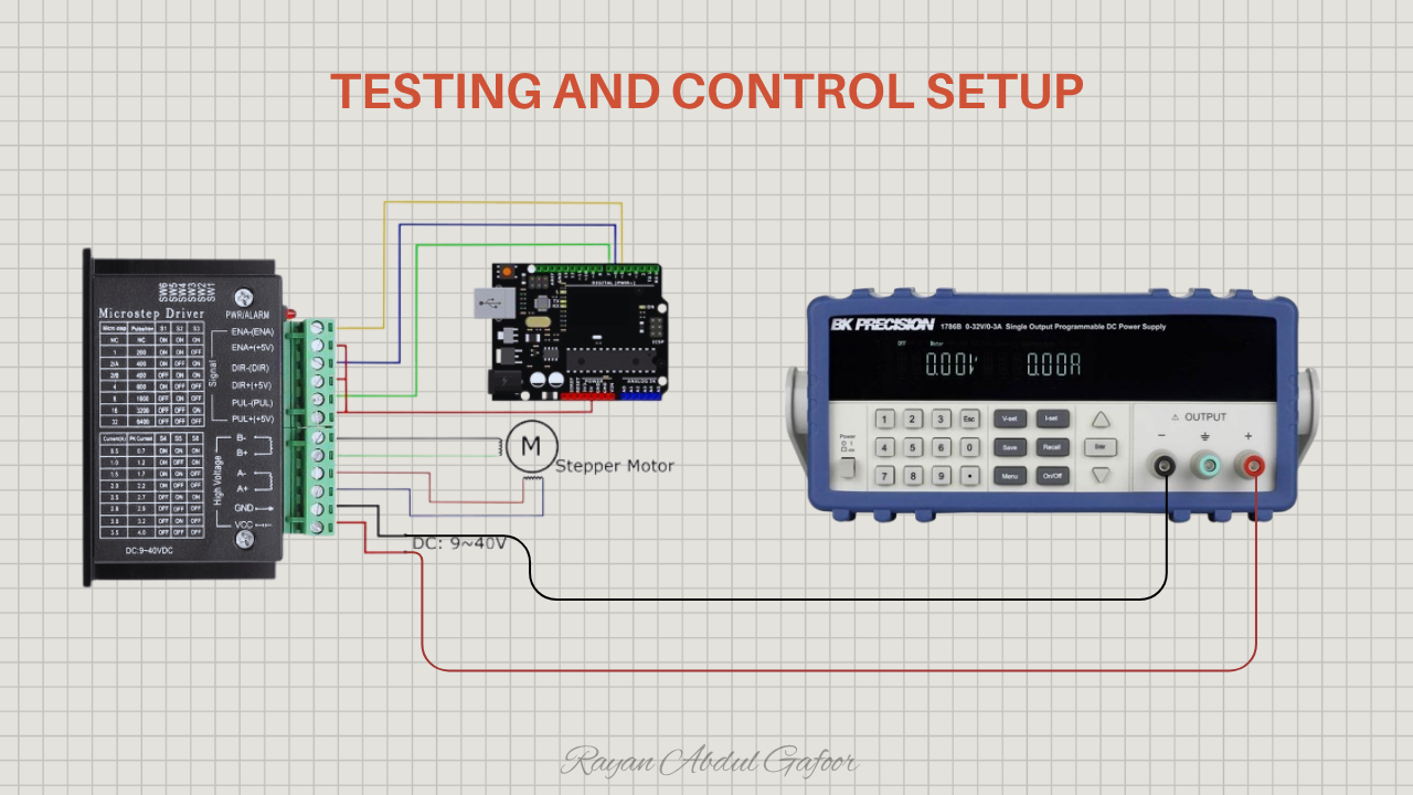
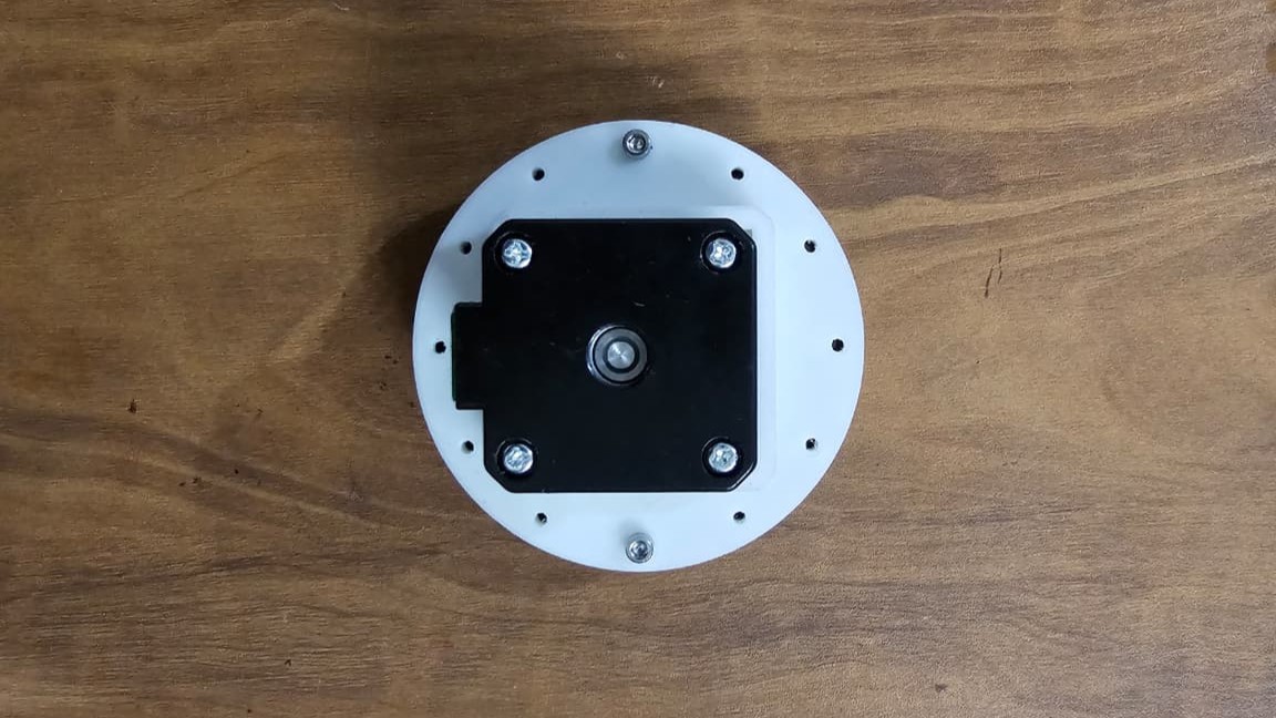
Testing and Control Setup
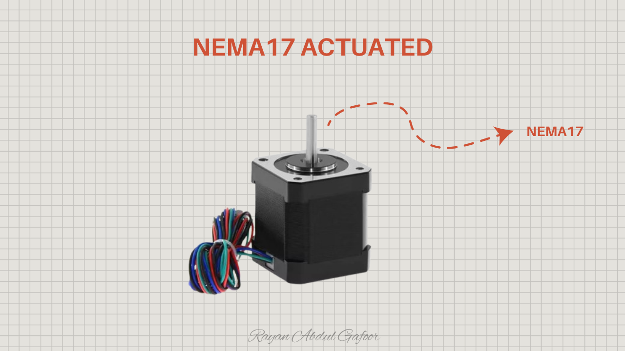
The NEMA17-driven harmonic drive was tested using an Arduino microcontroller and a TB6600 stepper driver, powered by a programmable power supply. The gearbox was modeled in Fusion 360 and fabricated using a Prusa i3 3D printer.
Calculations
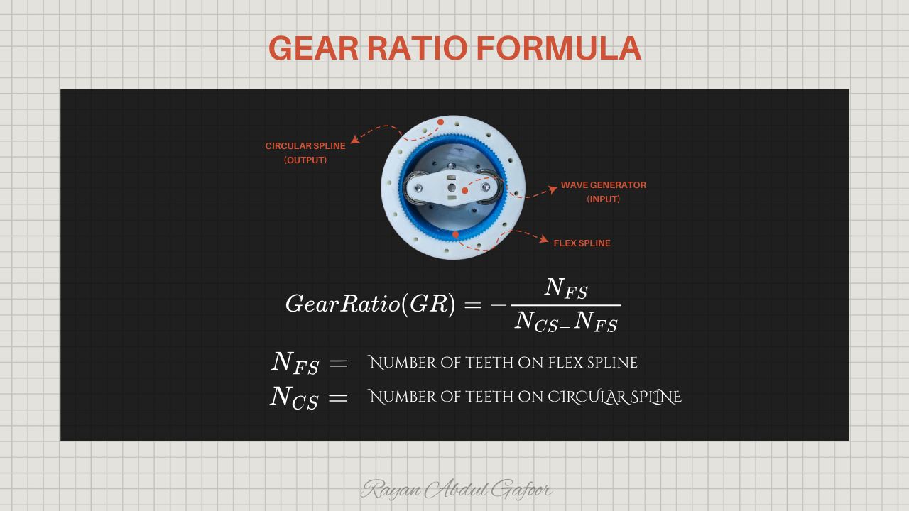
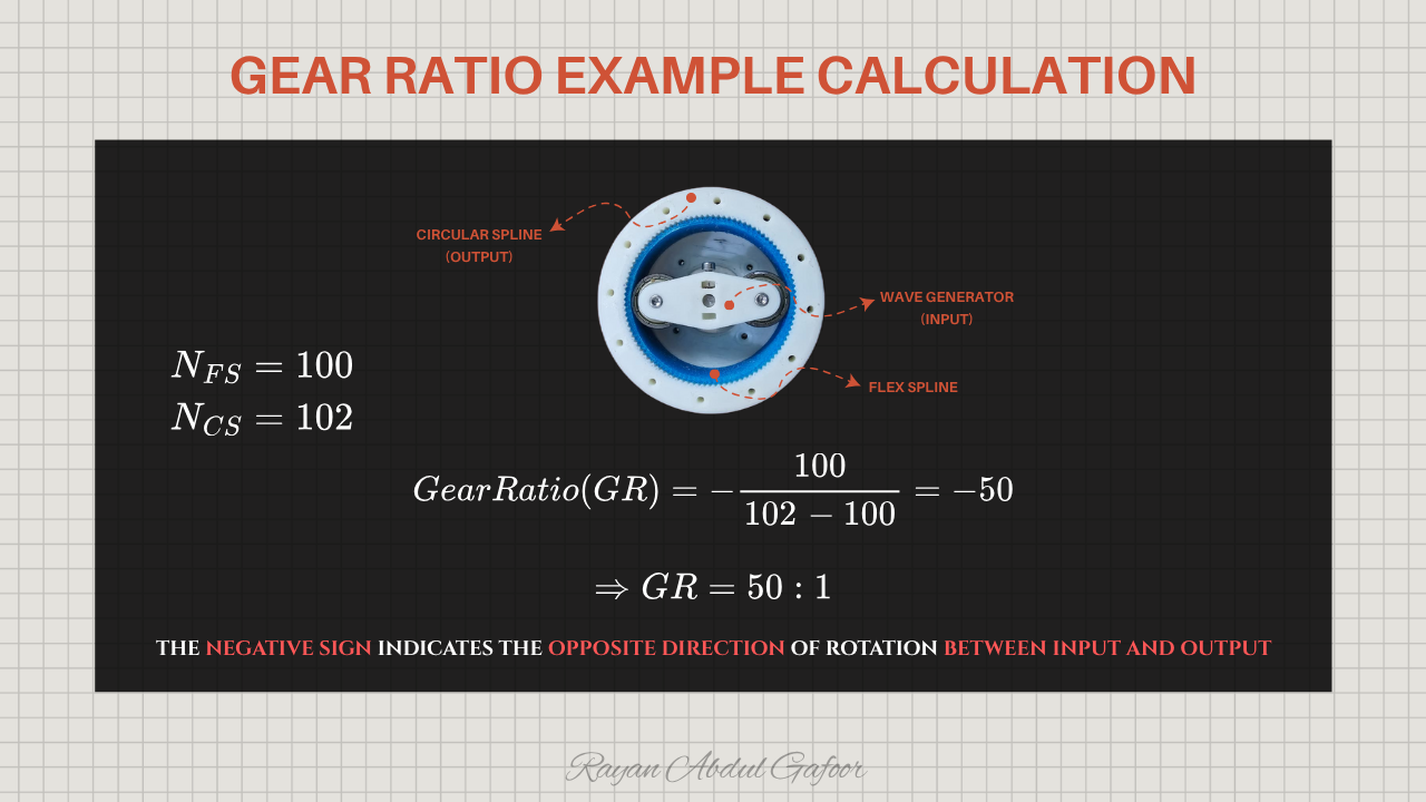
In a harmonic drive, the negative sign in the gear ratio simply means th e output rotates in the opposite direction of the input .
The wave generator (input) rotates in one direction and the flex spline has fewer teeth, it “lags behind” as it walks around the circular spline. This lag causes the flex spline/output to rotate in the opposite direction relative to the input. So if the input rotates clockwise, the output will rotate counterclockwise
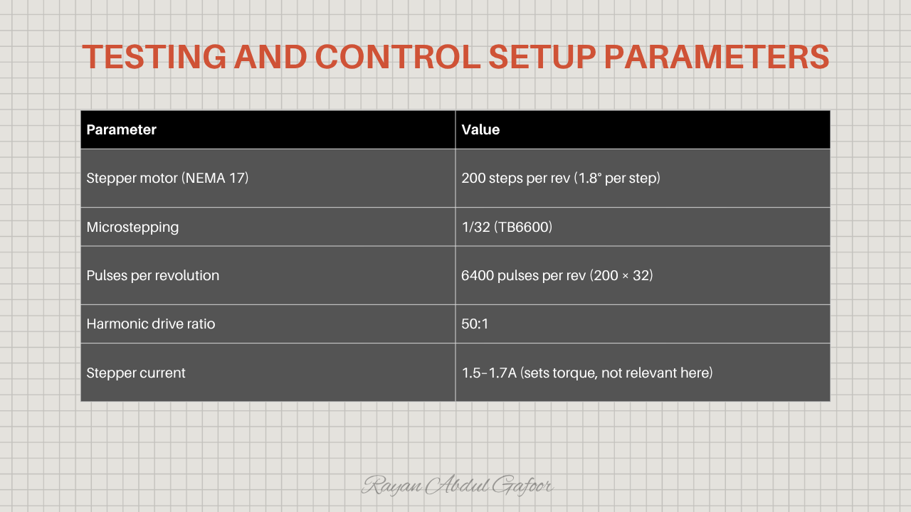
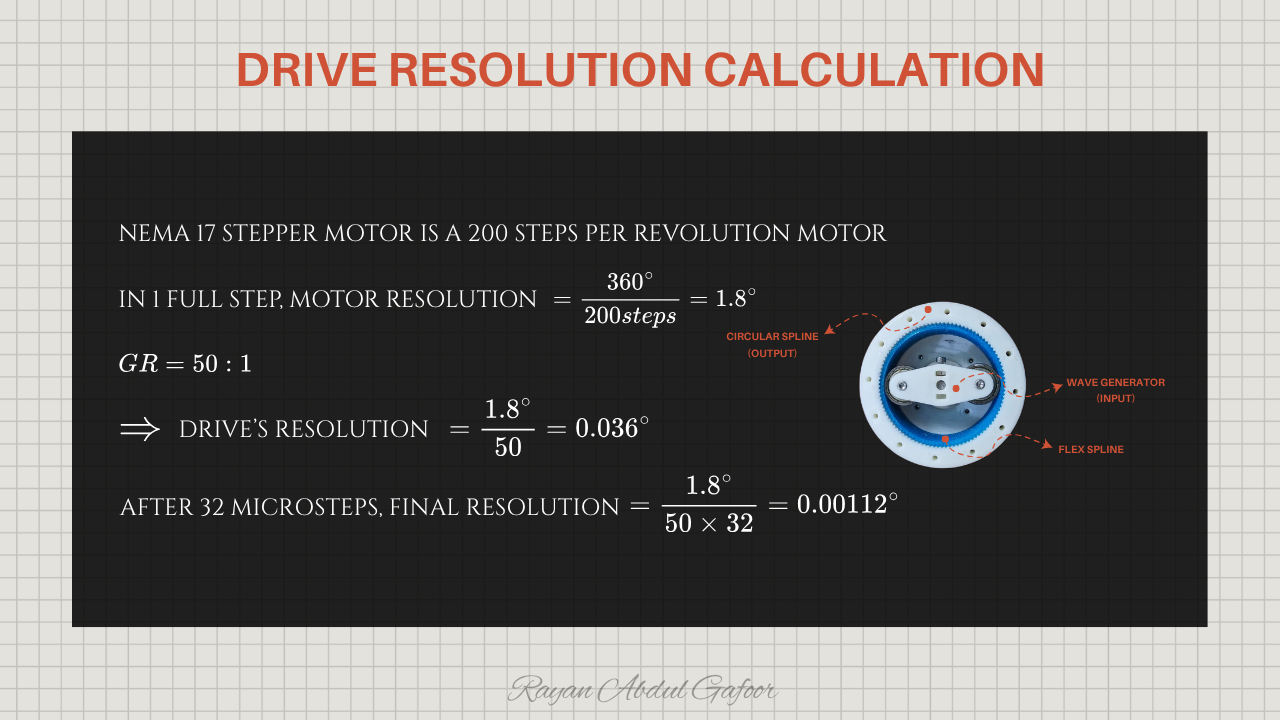
The setup uses a NEMA 17 stepper motor with 200 steps per revolution (1.8° per step), driven at 1/32 micro stepping through a TB6600 for a total of 6400 pulses per revolution, paired with a 50:1 harmonic drive.
The system achieves 0.036 degree per full step , and with 1/32 micro stepping , the resolution improves to 0.00112 degree , enabling very precise movement.
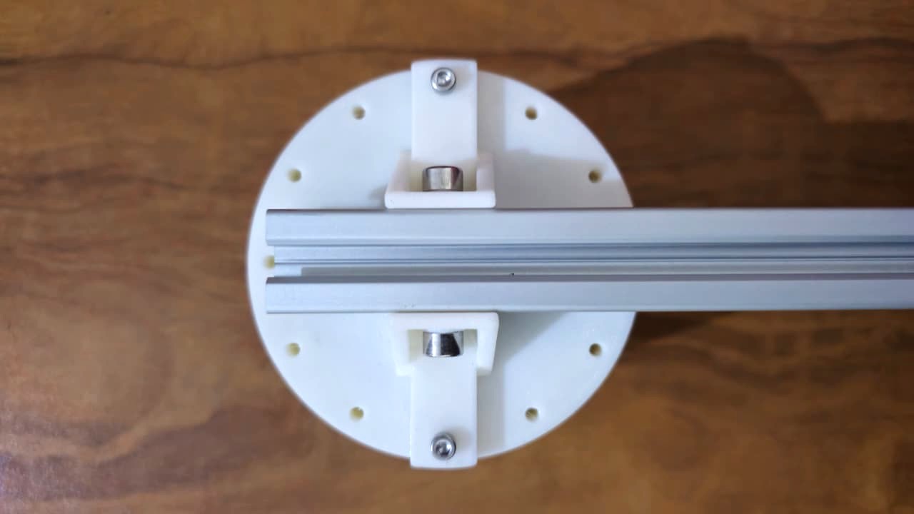
Hero Shots
Challenges Faced
The flex spline is printed in TPU while the other components are PETG. The drive performs accurately under axial loads, but it struggles with radial loads because the flexible TPU teeth tend to slip against the circular spline. This issue can be resolved by printing the flex spline in stronger, more rigid Nylon 6 using SLS technology instead of FDM.
The Flexspline in a Harmonic Drive is typically made of specialized alloy steel . This steel is chosen for its ability to be radially compliant while maintaining high torsional stiffness.
Advantages of Harmonic Drive
Very high gear reduction in a compact size
Zero backlash or extremely low backlash
Excellent positional accuracy
Smooth and precise motion
High efficiency (especially at low speeds)
Lightweight compared to other reducers with same ratio
Quiet operation
Disadvantages of Harmonic Drive
Limited torsional stiffness (flexible spline can deform)
Not suitable for high-speed applications
Fatigue of the flexspline over time, eventual wear
Lower torque capacity than same-size planetary gearboxes
Shock load sensitivity can damage flexspline
Efficiency drops at higher speeds
Not ideal for applications needing rigid, high-stiffness drive